Scientific American, December 28, 1901, pages 425-426:
THE SLABY-ARCO PORTABLE FIELD EQUIPMENT FOR WIRELESS TELEGRAPHY.
BY A. FREDERICK COLLINS.
The trend of thought in wireless telegraphy, just at present, seems to be in the direction of utilizing balloons and kites instead of the high masts or antennæ heretofore employed. Tesla expects to use small hydrogen bags to obtain the proper elevation in the forthcoming experiments at his Long Island station, and Marconi intends equipping his system at Cape Race with balloons of the same nature.
Striking results are reported to have been achieved by Dr. Slaby and his collaborator, Count d'Arco, of Germany, with a portable system of their own invention, the description, drawings and photographs of which I have been fortunate enough to obtain through the kindness of Dr. Slaby and the General Electric Company, of Berlin. The system these physicists have developed has received a tremendous impetus by the success of the inventors on occasion of an audience recently granted them by the German Emperor, when they received simultaneously two messages sent from different points. In this particular instance one of the transmitters was located at a distance of seven miles and the other two and one-half from the dual receiver where the exhibition took place. And this wonderful accomplishment has been the result of only five years of labor, for it was on the 11th of May, 1897, when the crucial tests of Mr. Marconi's then new wireless system were being made in England, that the Italian inventor was assisted by Prof. Slaby, who saw and believed in the ultimate useful future of spark telegraphy. To-day both he and Marconi are the inventors of improvements of the highest type, and these improvements are for the greater part specifically for the purpose of enabling messages to be sent and received by a number of operators in the same vicinity at one and the same time. Prof. Slaby terms this method of selectiveness multiple wireless telegraphy, and Mr. Marconi designates his means to this end under the caption of syntonic wireless telegraphy.
The apparatus of Slaby-Arco, while in the direct line of preceding systems wherein the spark of disruptive discharge of an induction coil radiates the waves, varies materially in detail from all others by virtue of the absolutely novel theory these workers have evolved and advanced concerning the action of the "wireless" or electric waves.
In the SCIENTIFIC AMERICAN under date of March 9, 1901, there was published a very complete report of Prof. Slaby and Count d'Arco's work along these lines, and unfolded the results of their progress up to that time, namely, the resultant action on and relations of the electric waves and the antennæ or vertical receiving and transmitting wires, and giving as the mechanical analogue of the stationary waves thus set up a vibrating steel wire. Since these phenomena have already been described, I will simply refer the reader to the paper mentioned for the fundamental principles involved, and take up the thread of the improvements made by the inventors since that time.
It will be necessary to refer to their older methods occasionally, in order to elucidate the value of the new, since many of the former difficulties have now been removed, as the following text, drawings, and photographs furnished by the Allgemeine Elektricitäts-Gesellschaft (General Electric Company) of Berlin will show.
 In the older description referred to, Slaby made use of a transmitter (Fig. 1), the antenna or vertical wire of which was connected to an induction coil, 2. All waves of a predetermined length would emanate from the end of the wire, 7, this being the point of the greatest amplitude, as shown by the dotted lines, and waves of every other length would find their greatest amplitude in the induction or choking coil, 2, and are thus not permitted to radiate into free space, but find their way down to the earth by the wire, 4. It will be observed that the antenna, 1, the coil, 2, the returning wire, 4, and the earth, 5, complete a circuit. Dr. Lodge, of England, has shown that while such an arrangement forms a very persistent oscillator of the waves, as an emitter it is very poor indeed. But this is not its only drawback. One of the great advantages of the Slaby receiver was the fact that any vertical wire, even though it was in the form of a lightning rod, could be employed to receive the waves; but the real value of this was lost, as the coil and parallel wire in transmitting were necessary, besides the obvious objection involved in elevating the coil.
In the new form of the appliance the inventors use as a transmitting antenna the one by which the messages are received; and another feature which is of the utmost importance, assuming that the deductions upon which the whole scheme is based are substantially correct, is that the rod may be used intact. Such an arrangement is shown in Fig. 2. A is the transmitting station and B the receiving station. The coil, 1, at A is an adjustable inductance, and by varying its length through the point, 2, the length of the antenna, electrically, may be given a suitable value which corresponds to the wave length of that produced by the induction coil. Now it will be seen that a lightning rod of any height may be made to conform electrically with the requirements of the wave-producing apparatus without mechanically altering its height.
The inductance coil, 3, and the capacity, 4, are also adjustable, and by varying their values a wave length emitted by the coil, 5, may be so modified or changed as to correspond exactly with the wave length represented by the vertical wire, 6.
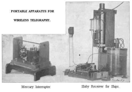
If the receiving antenna, B-1, is adjusted to the wave length of the transmitting antenna, A-6, the periods of oscillation in each are equal and a tuned system is the result. In this apparatus a Ruhmkorff coil, 5, is used with a centrifugal mercury interrupter, by which a steeper wave front of the disruptive discharge is secured. The receiving device usually consists of a Morse printing register, for on the Continent it is preferred to the ordinary sounder, probably for three reasons: (1) It is more easily adjusted; (2) It is often desirable to have a record; and (3) wireless messages are more easily read by sight than by sound, for the number of transmitted words per minute is rarely more than 12.
The relay, coherer, tapper and sounder are connected to the terminals, 5 and 5'. Here again the adjustable inductance coils, 2 and 7, serve to obtain a tuned or syntonized system corresponding to that of the transmitting station, 1. The coherer, 4, and the method of connecting it to the accessory apparatus is shown in the figure.
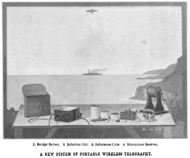
In one of the half-tones is shown a complete sending and receiving apparatus for a single station of the portable type. It consists of a portable storage battery (to the left) connected with an inclosed Ruhmkorff coil with key also inclosed and attached, the knob allowed to project in the photograph, three variable inductance coils, one box kite, one bird kite, coherer, receiver telephones and windlass. Fig. 3 represents diagrammatically the apparatus. In this form no great effort is made to tune the system, although the inductance coils are for this purpose; but it is intended for field and military work and for places where there is little possibility of another system or other interference. One of the greatest obstacles to the successful transmission of wireless messages during the early part of the British-Boer war was the heavy accouterments accompanying the instruments sent there by the Marconi Wireless Company of London. Masts of 100 or even 80 feet in height are much too cumbersome to be transported with the facility necessary in such all-important operations; and as the instruments themselves were useless without an antenna of this height, the whole scheme was abandoned and prehistoric signals of the Neolithic age were substituted in their stead. The portable Slaby-Arco system is arranged to overcome the difficulties that actual experience earned so dearly has pointed out.
 The portable induction coil (Figs. 3 and 4) is equipped with a vibrating interrupter of the usual type, 1, and the spark-gap, 2, is likewise of the ordinary character, being open in contradistinction to those inclosed in oil. The primary winding is shown in Fig. 4; 3 is the primary and 4 represents the secondary winding and terminals; 2, the spark-gap; 1, the interrupter; 5, the condenser of the coil; 6, the Morse key; and 7, the storage battery. One terminal of the secondary coil leads to the earth at a, and from the second terminal a conductor leads to the windlass, 9, where it is connected to the flexible metallic cord, 10, it in turn being attached to the box-kite, 11. The apparatus, 12, consists of what Prof. Slaby terms a microphone receiver. By this designation he distinguishes between two classes of receivers, namely, (a) those which require tapping to decohere the particles of metal and (b) those which are termed in this country self-restoring or self-righting; that is to say, that in the case of a the low resistance produced by the action of the electric waves will so remain until the normally high resistance is restored by some physical means, and in b where the restoring properties are self-contained, and the normally high resistance is instantly assumed the moment of cessation of the waves. Carbon possesses this property, likewise steel and iron, and so it is that the imperfect electrical contact discovered by Hughes in 1882, and which furnishes us with the modern telephone transmitter, now plays an exceedingly interesting part in wireless telegraphy in the form of the coherer, first made by Branly, of Paris, in 1890. Later Popoff used a microphone-coherer or a self-restoring coherer in which he mixed steel filings with carbon granules. The self-righting coherer for army and field telegraphy has a distinct advantage over those which require tapping, inasmuch as it does away with a vast amount of complicated and more or less delicate apparatus; again, the words can be received as rapidly as the operator can send. The improvement claimed by Slaby is that in his coherer of the microphone type a combination of steel and aluminium is used, either in the form of grains or of balls such as are used in telephone transmitters. In Figs. 3 and 4, 1 represents the steel aluminium coherer; 2 shows the cross section of the aluminium disks, and between them are placed the hardened steel balls. Atmospheric disturbances and electric waves emitted from lightning are avoided by placing the coherer in shunt to the wave system, 10 and 11 (Fig. 4), and not directly in series with it. The complete receiver is shown in Fig. 4.
The electromotive force actuating the telephone receiver consists of one dry cell, 6, only (Fig. 4) and this is connected in series with the double-pole switch, 7, and the choking coil, 8. By means of the key, 9. the current may be made or broken, the operator closing the circuit when listening to a message transmitted from another and distant station and releasing the key opening the circuit before transmitting a message. This is done to prevent the powerful radiations so closely to hand from welding the particles together and rendering the coherer worthless as a receiver for very feeble waves. When the electric waves from a distant transmitter are sent out the conductor cord, 10 (Figs. 3 and 4), receives the impulses and carries them to the microphone coherer, 1, when the high resistance is instantly lowered and now permits the passage of the weak battery current to flow through the coherer and also the telephone receiver, 16, for the period the waves are received, and the characteristic sounds of cohesion are heard through the variation of the electric current. Dots and dashes are distinguished by the length of time the cohesion exists or the variation of the current. In the half-tone the telephone receiver takes the form of a pair of watch-case or pony receivers connected by a flexible metal spring such as telephone operators wear during working hours.
The tuning of this receiver is accomplished by means of the inductance coil, 12 (Fig. 4), which is in tune with the receiving wire, 10. This coil is in shunt and is in tune with the emitted waves of the opposite station transmitter by the self-inductance, 11, and by the condenser, 13, grounded at 14, the capacity of which may be varied until the most suitable value is obtained by the handle, 15. The sensitiveness of a microphone coherer is much greater than that of a permanent coherer with the exception of the most carefully adjusted silver coherer, and for this reason it lends itself to the purpose of long-distance transmission; but since the maximum resistivity and minimum conductivity of a microphone coherer are not widely divergent, the current from the battery, 6, is insufficient to operate a relay, and therefore will not answer where a printed copy is desired.
The transmitter and the receiving apparatus utilize the same flexible cord as the receiving or emitting wire, and this angular antenna leads to the kite. Slaby employs various forms of kites for elevating the antenna; the American Blue Hill box-kite having a large sustaining surface is used in case of light winds; for stronger winds the box-kite is equipped with a much smaller surface. With winds so light that these kites cannot be used a special form of German kite having the shape of a bird is recommended. If there is no wind at all, small hydrogen balloons are provided having a capacity of one cubic meter. The weight of one station complete, including transmitters, batteries, receivers, auxiliary apparatus, etc., is 30 kilogrammes, and the greatest distance intelligible signals can be transmitted is 20 kilometers.