Western Electrician, May 16, 1903, page 385:
Clark Space-telegraph System in Detroit.
 About a year ago Thomas E. Clark organized in Detroit, Mich., the Thomas E. Clark Wireless Telegraph-Telephone Company. This concern, for some months, did space-telegraph work along the lakes in the vicinity of Detroit. Since that time, however, the Clark system has been rapidly developing, and the company has now practically decided upon a site on which to build a large factory. At this point a complete and powerful sending station will be equipped with dynamo capacity sufficient to send a wireless message many miles. The purposes of these stations will be primarily, however, to test the various types of apparatus which the Thomas E. Clark Wireless Telegraph-Telephone Company is manufacturing.
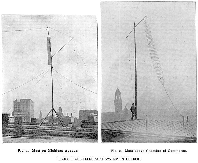
At the present time the Clark Wireless Telegraph Company is sending and receiving messages from two stations in Detroit. Fig. 1 shows the mast on the roof at 71 Michigan Avenue, while Fig. 2 shows the mast above the Chamber of Commerce, a number of blocks away. The sending and receiving, equipments, of course, are within the building. Fig. 3 shows a special type of instrument, which the company is now manufacturing and using in this service and which is particularly adapted for transmission from two to eight miles. It is to be remembered, however, that the distance of wireless transmission is largely dependent upon the energy behind the instruments: that is to say, the battery power.
The set of instruments shown in Fig. 3, as a receiving station, consists at the same time of a Clark sending coil, microphonic responder, telephonic receiver, batteries, retardation coils, etc., in fact, everything to make it a complete wireless-telegraph station, except the antenna and the coil batteries.
As seen in the illustration, the apparatus is a sending and receiving station in one, consequently this one set may be used, if desired, to illustrate wireless-telegraph work; that is, it can be separated into two parts and the sending apparatus taken to a distance from the receiver. Of course, the complete outfit would be the sending coil and receiver together, as illustrated, one set like the illustration, at each station.
The sender is a high-frequency Clark coil, of the size and type that gives service, with proper arrangement of aerial wires, to a distance of five miles.
The illustration shows the receiver in actual operation for taking messages in the Morse code, by sharp clicks in the telephone, clamped over the receiving operator's ear. It should be borne in mind that the instruments shown in Fig. 3 are not adapted for receiving on the tape. The tape-writing machine can, however, be combined with this outfit, and with this latter addition the apparatus can be used for receiving by sound and tape, as well.
The set of instruments shown in the illustration is designed particularly for practical work for service between private houses, islands and the shore, boats and yachts, from a few hundred feet distance to two miles. The set is also particularly adapted to school and college demonstrations, where, by slight changes in connections, anyone familiar with electrical apparatus can adapt this wireless set to the starting and stopping of a small motor, the lighting of an electric light, the exploding of a bomb, the ringing of a bell, etc. It should be understood, of course, that the outfit illustrated herewith does not include coil batteries or aerial wire. It does include, though, the local cells for operating the telephone. Specifications are, however, sent along with the apparatus advising those using it just what aerial wire capacity to employ and the battery power to obtain the best results under various circumstances.
