TOC | Previous Section: Chapter XXVII | Next Section: Chapter XXIX
History of Communications-Electronics in the United States Navy, Captain Linwood S. Howeth, USN (Retired), 1963, pages 319-335:
CHAPTER XXVIII
Post-War Research and Development of Radio Communication Equipment
1. POST-WAR PROBLEMS
The 1916 naval shipbuilding program was to have provided the United States with a fleet which would have been the most modern and strongest in the world.1 Within a few years following the termination of the war these new ships would require fitting with the most modern radio equipment our engineers could design.
Successful wartime developments such as the mica condenser, the vacuum tube oscillator, the improved vacuum tube detector and amplifier, indicated that vacuum tube transmitters and receivers held forth the greatest promise of success.2 A decision was made to make no further purchases of spark or arc equipments, but to spend the Navy's research effort towards the development of tube transmitters and to encourage commercial production of standardized types of tubes and tube transmitters suitable for all naval usages. A further decision was made to replace obsolescent apparatus with vacuum tube equipment as rapidly as research and development made it available and funds permitted.3
Opinion was still divided as to the desirability of having pure continuous wave output for all transmitters. In a very short time the expanded uses of radio forced the conclusion that nothing but this type of emission was satisfactory for a large number of ships operating in close proximity or for shore station transmissions.4
2. POSTWAR RESEARCH AND DEVELOPMENT
Research and development problems included the expansion of the radiofrequency spectrum to provide the additional circuits required for the fleet's strategical and tactical uses of radio; the provision of means for simultaneous reception of several different frequencies with the receivers using the same antenna; the development of higher powered tubes and transmitters; the elimination of the transmission of additional undesired frequencies; and the development of lighter weight equipment for aircraft, and further reduction in aircraft-generated noise and ignition interference.
Research in vacuum tubes was carried on primarily by the General Electric Co. and the Western Electric Co. under Navy insistence, guidance, and financial assistance.
Rapid demobilization limited the work of the Radio Test Shop of the Washington Navy Yard to that of assisting in the design of tube transmitters, the provision of receiving systems, and the development of the uniwave key for the arc transmitters. Research and development at other navy yards was drastically curtailed, although the Philadelphia Yard was able to effect improvements in direction finding apparatus. The Naval Radio Research Laboratory returned to its former work in fundamental research and obtained considerable information concerning the origin of the static caused by the earth's magnetic field. Active research and development was carried on by the Naval Aircraft Radio Laboratory which, still under the direction of Taylor, had been moved from Hampton Roads to the Naval Air Station, Anacostia, D.C. The work of this Laboratory was a continuation of the wartime research and development carried on at Hampton Roads, with additional tasks assigned involving studies in multiple transmission, and reception, and investigations directed toward increasing the width of the usable radiofrequency spectrum.
3. DISCOVERY OF THE PHENOMENON OF RADAR
In carrying out the last-mentioned task, Taylor, assisted by Mr. L. C. Young, had, by 1922, pushed his experiments to frequencies of 60 megacycles by utilizing superhetrodyne receiving circuits. While working at these frequencies during the summer of that year, Taylor and Young first noted the reflection of signals from vessels passing on the Potomac River and discovered the possibility of obtaining the ranges and bearings of these vessels. This was in fact the discovery of radar, called by Taylor at the time "the detection of enemy ships and aircraft." In September 1922 he addressed a letter to the Bureau of Engineering requesting authority to exploit this discovery stating that the equipment should work during darkness and low visibility as well as on a bright sunny day. At that period of its development, relative movement between the radar equipment and its target was necessary in order that the latter might be detected. The ultimate development of pulse transmission eliminated this requirement. Taylor was not authorized to continue his radar research at that time.5
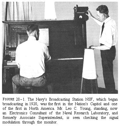
4. THE NAVY BROADCAST STATION
Public Law Number 264, approved 13 August 1912, required all amateur stations to utilize frequencies higher than 1,500 kc. In the course of their experiments, Taylor and Young contacted numerous amateurs working in the spectrum above this frequency and found that they had a wide circle of listeners in that group. In order to increase the interest of the amateurs, they commenced broadcasting music in 1920, and thus became one of the earliest broadcasting stations. The U.S. Public Health Service became interested in this medium and, with the approval of the Navy Department, commenced broadcasting public health lectures over the laboratory station twice each week.
This broadcast station, with the cooperation of the telephone company, was the first to put the voices of a President, a Chief Justice, a Senator, and a Congressman on the air. President Harding and Chief Justice Taft broadcast during the dedication of the Lincoln Memorial on 30 May 1922. Senator Lodge was the first Senator to broadcast. He gave a short talk intended for a group in his home town of Nahant, Mass. Unfortunately, it could not be restricted to this group, a fact which made the Senator quite indignant.6 Congressman John L. Cable of Ohio spoke over the station 10 February 1922. The first broadcast of the House of Representatives emanated from the Laboratory. This last important broadcast occurred in the early part of December 1922 when, for the first time in history, a President's message to Congress was put on the air. Following this, there were so many special requests that broadcasting began to interfere with research. The broadcasting activity was transferred to Arlington where it was restricted to programs in the public or the Navy's interests.7
5. EARLY POSTWAR VACUUM TUBE TRANSMITTER DEVELOPMENTS8
During the war, intensive tube development had been conducted by the General Electric and Western Electric Cos. guided by an advisory committee consisting of representatives of the Army, Navy, Bureau of Standards, General Electric Co., Western Electric Co., Westinghouse Electric and Manufacturing Co., and De Forest Radio Telephone Co. Much was accomplished towards the standardization, increased ruggedness, and longer life of tubes, but little was done to increase their power output. Towards the end of the war, the British developed a 2-kw. vacuum tube transmitter, but the most powerful one developed in this country by that time was 250 watts.
On the termination of the war, the commercial companies refused to continue the development of the tube transmitter because they considered it of little commercial value. In late 1919 the Bureau of Engineering decided to spend $250,000 for tube transmitters to create incentive for the commercial companies to continue development. Specifications were drawn up for two sets, the Model TC for installation on battleships, and the Model TD for use by air stations in communicating with aircraft. The specifications for the Model TC were based on the British 2-kw. set, with the addition of voice modulation. Its specifications called for an output of 150 watts, while those of the TD called for 750 watts. Twenty of the TC and 15 of the TD were contracted for with the General Electric Co., the low bidder. The total cost of these equipments was approximately $125,000.9
In order to provide the Western Electric Co. with incentive to continue development, it was given a contract for 20 sets of Model TB voice modulated equipments. These were to be installed in battleships for the exchange of gunfire control information within a division of such ships.
At this time the Naval Aircraft Radio Laboratory developed the SE 1345, a lightweight transceiver for observation planes.
The performance of all these transmitters was disappointing. Unsolved technical details caused them to give unreliable service. Before the delivery of these equipments was effected, 34 Model TE transmitters, configured to the "S" type submarines which were nearing completion, had been placed under contract with the General Electric Co. It was an improvement over previous models but was not thoroughly satisfactory because space limitations made it inaccessible and required a compactness necessitating the use of insufficiently rugged components. The Model TF had also been placed under contract for equipping converted aircraft tenders. It was similar to the TE, but proved to be more reliable since less stringent requirements for compactness permitted more rugged construction.
6. POSTWAR VACUUM TUBE IMPROVEMENTS
On 20 January 1920 the Bureau of Engineering held the first of a series of conferences with representatives of various firms in an endeavor to stimulate their interest in the development of higher powered tubes and in the standardization of the characteristics of existent types. At a later conference, held on 31 March, the Bureau representative stated that, in the future, all 50- and 250-watt tubes must be interchangeable with the General Electric Co.'s CG 1144 and CG 916 respectively. It was further recommended that the Western Electric Co. redesign its latest 250-watt tube by increasing its power to 500 watts and making it interchangeable with CG 916. At this same conference a request for the development of a 1,500-watt tube was made, and company representatives advised that future vacuum tube transmitters for the Navy must be designed to include telephonic operation. To encourage the manufacturers, it was stated that 30,000 type SE 1444 receiving tubes would be required within the next years.10
This conference marked the turning point in tube development. In early 1921 intensive research was instituted by both the General and Western Electric Cos., which, with the advent of radio broadcasting, saw increased commercial value in tube transmitters.11 By early 1921 the General Electric Co. had developed a 1-kw. tube.12 By midsummer of the same year it was rumored that the Western Electric Co. engineers had developed a metal tube that could deliver an output of 20 kw.13 The latter proved to be a water-cooled tube, rated at 5 kw., but which, upon test, gave an output of about 3.5 kw. The General Electric Co. had also developed a similar tube. In late 1921 the Bureau requested both companies to attempt to avoid the need of water cooling.14 A few months later, the General Electric Co. produced a tube which they rated at 5 kw. but which the bureau accepted at 3 kw. and designated CG 1353. The contract price of these tubes was $353 each.15 In July 1922 the General Electric Co. supplied the Radio Corp. with 20-kw. tubes for installation at its new radio station on Long Island.16 This was also a water-cooled tube. It was first purchased for naval use in 1924 for converting the 30-kw. spark transmitter at Arlington, Va., into an alternating current vacuum tube set.
7. NAVY ALTERNATING CURRENT VACUUM TUBE TRANSMITTER DEVELOPMENTS17
On 15 May 1921, Senator Borah of Idaho, alarmed at the annually increasing amounts of the naval appropriations bills, proposed an amendment to the current one authorizing the President to invite the chief naval powers to a conference in Washington to discuss ways and means of ending the costly naval competition. This amendment was passed without a dissenting vote and resulted in the Washington Limitation of Arms Agreement.18 This agreement created the utopian illusion that the world was "safe for democracy" and caused a sharp reduction in naval appropriations.
Because of the drastically reduced naval appropriation, insufficient funds were available to finance the tube transmitter development by commercial companies. The model TL transmitter, designed and developed by naval radio engineers, was finished in 1922 and tested in the winter of 1922-23 on the U.S.S. Wyoming. It proved to be very satisfactory. Available spark transmitter power equipment was utilized, thereby reducing the cost of each of these 6-kw. alternating current transmitters by $17,000. Enough of the old spark transmitters were remodeled to provide one Model TL for each battleship. An expected handicap to these equipments was the cost of the short life tubes. It was decided that four tubes would be purchased for each set as a year's allowance, with the understanding that after these were expended the transmitters would not be used. However, before they were installed in the battleships, the Western Electric Co. was able to provide an improved version of their 5-kw. watercooled tube. Designated CW 1887, it carried a life guarantee of 1,000 hours.19 In service some of them lasted as long as 10,000 hours.20
At the time the TL was being designed and developed, 100-watt alternating current transmitters for submarines (Model TM) and battleships (Model TO) were being constructed by remodeling spark sets and using tubes as oscillators in lieu of the spark. These Model TM transmitters cost only $400 each and proved far superior to the Model TE. The Model TN, a 6-kw. set, was constructed for shore station use.
Later, a tube transmitter utilizing old spark transmitter components was designed for use on destroyers and light cruisers and the spark gaps at shore stations were replaced by oscillating tube components. Other such self-rectifying transmitters were developed utilizing the 500-cycle supply with modified spark transmitter transformers.21 These filled the breach prior to the final satisfactory development of reliable tube transmitters permitting the Navy to eliminate most of its spark equipment, and thereby setting an example for the world to emulate.

8. POSTWAR RECEIVING EQUIPMENT DEVELOPMENT
The immediate postwar work assigned the Radio Test Shop at the Washington Navy Yard was the standardization of shipboard receiving installations with emphasis on increased selectivity so that more circuits could be employed simultaneously. Existing Navy-designed components were assembled and designated Models E, F, and R. The Model E equipment consisted of one low and one medium frequency receiver arranged to permit both to be used simultaneously on one antenna. The Model R, a single receiver installation, was primarily for use in destroyers and other smaller craft. The Model F was also provided with a single receiver but had additional components which permitted it to be used for double reception by using one of the receivers of the Model E installation. Battleships were fitted with both Models E and F; the cruisers and destroyer and other tenders with the Model E. All three models utilized the complicated and temperamental acceptor-rejector circuit copied from that used by the Royal Navy.22
None of these equipments met the requirements for submarine installations. In September 1919 the Navy, with the cooperation of the Edison Society, the United States Bureau of Standards, the Hammond Laboratory, and the Marconi Wireless Telegraph Co. of America, commenced experiments to determine the essential factors involved in the transmission to and reception by submerged vessels. Various types of antenna were used, including the conventional flattop, the trailing antenna, and the loop arrangements of Willoughby and Lowell of the Bureau of Standards.23 It was discovered that the very low frequencies suffered much less attenuation in sea water. The radio station at Nauen, Germany, distant 3,234 miles, transmitting on a frequency of 24 kc., was received by a submerged submarine off New London, Conn. This submarine was fitted with two multiloops located at right angles to each other with the tops of the loops 14 feet below the surface. It was also discovered that, with the submarine at periscope depth, any high-powered station transmitting on a very low frequency could be received at distances up to 3,000 miles. Continued experiments proved that single turn loops were as efficient as multiturn ones and that, at a particular frequency and specific depth of receiving antenna below the surface, the effective range of a signal was directly proportional to the power delivered to the transmitter antenna.24
Based upon this information, the Model RA receiving equipment was designed for submarine installations. It utilized standard Navy components and a specially designed loop tuning system, and covered the frequency range 16-1200 kc.
Following the development of the Model RA receiving system, the Radio Test Shop designed Models RB and RC shore station receiving equipments. The Model RB covered the frequency range 10-50 kc. It was made up of available components augmented by a special barrage tuning unit and a new Navy designed receiver, the SE 1530. The barrage tuning unit permitted the use of single wire antenna of about 200 feet in length combined with a loop 8 feet square wound with 48 turns. The new receiver was the first to be designed using an additional circuit, the intermediate, interposed between the primary and secondary circuits. This eliminated the necessity of broadly tuning the secondary circuit.25 The Model RC was similar and covered the remainder of the usable spectrum up to 2200 kc.
Destroyer operations on the scouting line indicated an increase in circuit requirements over those contemplated when the Model R equipments were installed. Since insufficient space was available for the Model E the Radio Test Shop designed the Model RD as a replacement. This system utilized two receivers and covered the frequency range 25-1200 kc.
None of these systems can be considered as other than "stop-gaps". The experience gained during the war and the increased knowledge of "radio phenomena" would quickly result in more advanced equipment to be discussed later.
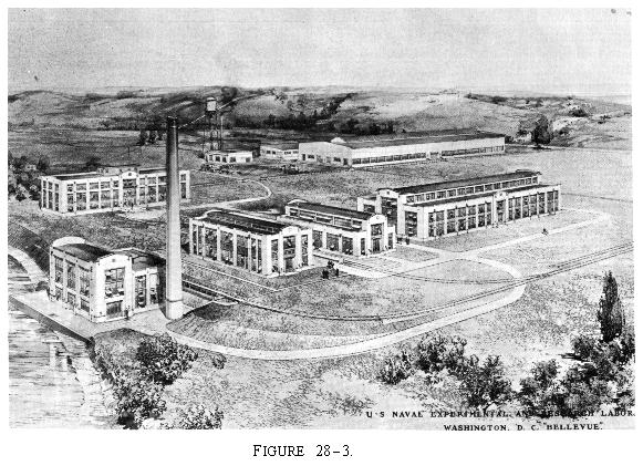
9. ESTABLISHMENT OF THE NAVAL RESEARCH LABORATORY
In 1916 Congress, acting upon the recommendation of the Naval Consulting Board of the United States, under the chairmanship of Thomas Alva Edison, appropriated funds for the establishment of a naval research laboratory. Construction was immediately started upon the building at Bellevue, D.C., but this was stopped upon the conclusion of the war. Congressional economy held the project in abeyance for several years, but it was eventually completed and established on 1 July 1923. At that time the research and development functions of the Naval Radio Laboratory, the Naval Aircraft Radio Laboratory, and the Radio Test Shop at the Washington Navy Yard were combined and formed the Radio Division of the Naval Research Laboratory. Dr. A. Hoyt Taylor was designated division superintendent and Dr. J. M. Miller assistant superintendent. Miller had been associated with Dr. Austin and was an authority on vacuum tube theory and precision measurements. Austin's health was not good and, to the great regret of all in the Navy who knew him, he had resigned shortly before. His contributions had enriched the knowledge, not only of naval radio, but of the world in general. He continued his studies on high-frequency propagation but devoted more and more of his time to the affairs of the International Scientific Radio Union.
The Radio Division of the U.S. Naval Research Laboratory consisted of the following groups and directors:
| Precision measurements | | Dr. J. M. Miller |
| Transmitters | | Mr. L. A. Gebhard |
| Receivers | | M. T. McL. Davis |
| Aircraft radio | | Mr. C. B. Mirick |
| Direction finders | | Mr. W. B. Burgess |
| General research | | Mr. L. C. Young |
10. RESEARCH AND DEVELOPMENT OF HIGH FREQUENCY EQUIPMENT
One of the initial tasks assigned the Radio Division of the Laboratory was the continuation of the Naval Aircraft Radio Laboratory investigation of the use of higher frequencies. To accomplish this, a transmitter was developed to cover the frequency range between 1500 and 2500 kc. This transmitter was later modified to an upper limit of almost 3000 kc. Considerable difficulty was experienced in preventing wobbling with the attendant loss of signal when using the heterodyne method of reception. It was discovered that, unless the transmitter and receiver were completely shielded, a slight movement of the operator's hand could produce a change in frequency of as much as 10 kc. Other effects tending to reduce stability were variations in temperature, applied voltage, humidity, and variations resulting from movements of either the transmitting or receiving antenna.26 Unless something could be developed which would increase frequency stabilization, high-frequency radio would be of little value to the fleet.
At the time the common method of frequency control was by use of a power amplifier circuit which provided a stable frequency control for a small low-powered transmitting tube if adequate shielding was used and a nonfluctuating voltage was applied. The output of this circuit was then applied to the grid of a higher powered amplifier thereby controlling the frequency of the output circuit which was coupled to the antenna. It was discovered that the power amplifier would, if operated on the same frequency as its exciting master oscillator, go off on its own and oscillate on some frequency differing from that desired. Balancing circuits were necessary to control the amplifier.27
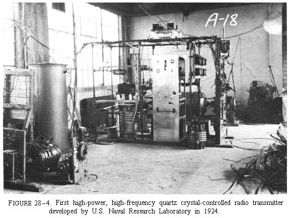
In continuing with the task, Taylor and Young constructed another transmitter which would operate on a frequency approximating 5700 kc. A master oscillator excited a power amplifier circuit coupled to the antenna and to a counterpoise. The filaments of the tubes and the motor generator, supplying 2,000 volts of direct current, were operated by storage batteries thus reducing voltage fluctuations. Though the stability of this transmitter was good, it was not good enough for fleet communications. It was decided to use piezocrystal control to obtain the necessary stabilization. The consultant services of the two best authorities on quartz crystal, Dr. Karl Van Dyke and Mr. Walter G. Cady, were obtained during the summer of 1924. With their aid the transmitter group designed and built the world's first high-power crystal-controlled transmitter during that year. It delivered 10 kw. to the antenna circuit at a frequency of 4015 kc. and was successfully used on the extremely difficult circuit with London for several years.
Meanwhile, the receiver group designed two new receivers, a low frequency, RE; and the intermediate frequency, RF. These receivers served many years before better ones, meeting naval requirements in the low and intermediate frequency ranges, were designed. But receivers were required for still higher frequencies. Many "soapbox models" were built. These were sufficiently sensitive but too complicated and insufficiently rugged for service use. In 1924 Mr. M. P. Hanson designed the first to meet naval requirements. The receiver group developed and constructed the initial one. It was successfully used by the U.S.S. Shenandoah, a dirigible, on her 1924 cruise from Lakehurst, N.J., to the west coast and return. Designated RG, it was the first high-frequency receiver installed in the fleet.28
11. CONTINUED RESEARCH IN THE USE OF HIGHER FREQUENCIES
During the period radio amateurs already numbered in the thousands, and they were becoming increasingly interested in using the higher frequencies. In this they were ably guided by the ranking amateur association, the American Relay League. Although interests of the amateurs lay more in achieving distance and in the number of contacts they could make than in stabilized frequency operation, their cooperation with the Naval Research Laboratory was of great value and led directly to the solution of the behavior of short waves. It had been noticed that frequencies between 2000 and 4000 kc. carried much further during darkness than during daylight and that frequencies between 4000 and 12,000 kc. were better for daylight use. Endeavoring to discover the reasons underlying this, the Laboratory, in conjunction with Mr. John L. Reinartz, owner of an amateur experimental station in the vicinity of Hartford, Conn., commenced experiments. Reinartz, who later was commissioned a commander, USNR, had a continuously variable transmitter covering a wide band of frequencies. The Laboratory had several transmitters, each with two or three different crystal-controlled frequencies, available for simultaneous transmissions. The normal procedure was to establish communication between the two stations on medium frequencies after which Reinartz would gradually raise his frequency while the Laboratory made observations and notified him when his signals ceased to be readable. Usually the signal strength increased until a rather high frequency was reached which varied from day to day and with the seasons, whereupon the signal strength suddenly dropped to zero. It so happened that Mr. M. J. Lee, later a captain, USNR, operating an amateur station in Orlando, Fla., listened during these operations and noted that when the signals ceased to be received in Washington that he continued to receive them in Orlando. He notified the Laboratory of this, after which his station was added to the experiment. Many tests were conducted, the results indicating the existence of a zone of silence, which varied with the frequency in use. This was the discovery of "skip distance." This phenomenon did not fit in with older wave propagation theories and led to their modification by Taylor and Dr. E. O. Hulbert of the Physical Optics Division of the Research Laboratory.29
Considering the "skip distance" phenomena, high-frequency radio could not be used in the fleet in the same manner as the lower frequencies had been utilized. The custom had been to assign units specific frequencies for use day or night, summer or winter. However, the power required for the higher frequencies was so small compared with that for the low and medium frequencies and the signal-to-noise ratio so much more favorable to the higher frequencies that the Navy Department favored shifting to this portion of the frequency spectrum. The fleet was less inclined to do so because of its need for absolute reliability.
12. FLEET TESTS OF HIGH FREQUENCY RADIO
During early 1925, the Fleet was preparing for a cruise to Australia. It was decided to make an experimental installation in the Fleet flagship, the U.S.S. Seattle, where Hooper was again serving as Fleet Radio Officer. He was not convinced of the usefulness of high frequencies at that time. Mr. Frederick Schnell, a naval reserve officer, Traffic Manager of the American Radio Relay League, was ordered to active duty and assigned to assist Hooper in the experiments which were to be conducted during the cruise.
The installation in the Seattle consisted of the Laboratory transmitter operating on a frequency of 5700 kc. and an RG receiver. Snell was permitted to install his personal transmitter which covered a wide frequency band. In addition to the one at the Laboratory, RG receivers were installed at San Francisco, Honolulu, and Balboa, C.Z.30
The American Relay League made arrangements for the cooperation of amateurs all over the world. For handling official traffic, the Naval Research Laboratory was designated the principal receiving station.31
En route from San Francisco to Honolulu numerous tests were conducted. It was discovered that many electrical devices aboard ship emitted radiations that interfered with reception. The rolling and pitching and the vibrations of the ship increased the difficulties in the use of the apparatus which required critical tuning. Despite these conditions, fair results were obtained and these results improved as the operators became more proficient. During the best transmission hours, 2330-0800, zone-plus-5 time, little difficulty was experienced in handling direct communication with Washington, even during the period when the fleet was in Melbourne, nearly 10,000 miles away.32
Following these tests, the Commander in Chief recommended the addition of high frequencies to the fleet frequency plan and that shore stations be equipped to transmit to the fleet on frequencies not higher than 9000 kc. The Bureau disregarded the latter and immediately made plans to equip 28 shore stations with transmitters with an upper frequency limit of 18,000 kc. Within a few years the U.S. Fleet was provided with far more reliable equipment than any fleet in the world.33

13. IMPROVEMENT TO THE ARC TRANSMITTER
During the war the Navy had invested a considerable sum in arc transmitters, and economy dictated their continued usage until such time as they became uneconomical in operation. The early high-powered (30 kw. and above) arcs were crude devices compared with present-day standards. The means of keying them was by short circuiting some of the turns of the antenna helix or by changing the capacity of the antenna. Either of these methods caused a change in the emitted frequency. Thus, at the time a signal was being transmitted, the antenna emitted one frequency and, at other times, another, called the spacing or compensating frequency.
The key first provided to operate the changes in antenna inductances or capacities was a crude device known as the "barrel key." It consisted of a wooden lever about 8 feet long pivoted to the top of a large barrel, filled with water. From the end of the lever a heavy wire led down into the barrel where it could be made to contact a heavy metal plate at the bottom. This barrel key was connected across the ground and the insulated lower half of one of the antenna support towers. Messages could be transmitted by it at the rate of about eight words a minute provided a sufficient relay of operators were available for pumping. In 1916 Eaton devised a multicontact key which provided one contact for each turn of the helix. This solved the keying problem insofar as manpower and speed of transmission was concerned but did not eliminate the compensating frequency.34
In addition to this compensating frequency the arc also emitted numerous harmonics of both the transmitting and compensating frequencies and, additionally, its tone was quite mushy. With the reactivation of amateur activities in 1919 and the advent of broadcasting in 1921, considerable criticism was justly leveled at the Navy because of the interferences they caused. A research and development problem was established to devise means of eliminating the compensating frequency, the harmonics, and of decreasing the mush.
The Federal Telegraph Co., Gunner Kenny in the U.S.S. Ohio, Cohen and Eaton at the Radio Test Shop, all worked on the development of a uniwave key. Cohen developed one which cut resistance in and out of an absorbing circuit but it was too critical to be of practical use. Eaton later devised a satisfactory keying system which retained the absorbing circuit but utilized a bank of noninductive resistance units between the transmitter and the antenna and absorbing circuit. The absorbing circuit was connected to the arc through a transmitting key resistor. When the keying contact was open the absorbing circuit prevented the antenna from radiating, thus eliminating the compensating frequency.35
To eliminate harmonics two methods were attempted. One was the use of a high pass filter in shunt with the arc, the other was to couple the arc to a rejector circuit in series with the antenna. The first method, devised by Radio Aid Buttner, proved the simpler, while the second, designed by Radio Aid Hallborg, gave more efficient operation. On 11 February 1922 a conference was held in the Bureau to plan further steps for the elimination of harmonics and reduction of mush. It was recommended that further experiments be conducted on the two systems. During these tests it was discovered that the Buttner circuit reduced the efficiency to an unsatisfactory extent and this necessitated the adoption of the Hallborg method despite its being more difficult to tune. Interference created by the arc transmitter was successfully eliminated by the adoption and installation of this circuit.
14. THE U.S.S. OHIO--RADIO EXPERIMENTAL SHIP
In August 1919 the obsolete U.S.S. Ohio was assigned to the Bureau of Engineering as an experimental ship to facilitate the development and service testing of new radio equipment and installations. This was done to eliminate the annoyances occasioned by conducting experiments on ships actually engaged in training exercises.
The Ohio was degunned and refitted for her new role at the Navy Yard, Portsmouth, Va. The original radio room was left unchanged to handle the ship's normal radio traffic. Two additional large radio rooms were located below decks. One was fitted with the transmitters which included a 20-kw. arc, a 5-kw. arc, and a 5-kw. spark, and a motor buzzer set. The other was equipped with models E, F, and G receiving systems. Two large antenna trunks, one of steel, 3 feet in diameter, the other of copper, 30 inches in diameter, were installed between the main deck and the experimental transmitter room. Special topmasts which could be varied in height in increments of 5 feet were added to the cage masts. These provided a maximum height of 180 feet above the waterline.36
The refitting was completed in April 1920 and the Ohio was stationed at Annapolis under the command of Capt. John F. Halligan, USN, the commanding officer of the Naval Experimental Station. Lt. H. F. Mennerati, USN, a most capable, practical radio engineer, was the executive officer, first lieutenant and radio officer.
The Bureau immediately assigned numerous tasks to the ship among which included:
Service tests of new radio equipment;
Improvement of the standard radio installation in battleships to provide maximum simultaneous transmission and reception;
Determination of minimum size and type of material for radio trunks required for below-deck installation of 20-kw arc transmitter;
Measurements of antenna constants under all conditions and a study of their natural variations;
Measurements of antenna and trunk potentials for arc and spark transmitters at various powers;
Comparative tests of arc transmitter keying methods;
Determination of stresses in shipboard antennas under service conditions;
Comparison of the CW 936 with later radiotelephone sets as to interference on the same and nearby ships;
Experiments with acceptor-rejector circuits;
Experiments with loop antennas for reception of short range transmissions; and
Determination of the absorption, shadow, and reradiation effects of cage masts.37
This was a monumental assignment for a ship with such a drastically reduced crew that even the mess attendants were pressed into service to assist in conducting the experiments. Mennerati did much to increase practical knowledge concerning shipboard radio installations especially those involving antenna constants, arc transmitter keying, improved battleship installations, and the effects of cage masts and other closed circuits. He could not completely solve all the assigned problems due to interferences beyond his control.38
15. USE OF REMOTE RADIO CONTROL OF SURFACE VESSELS
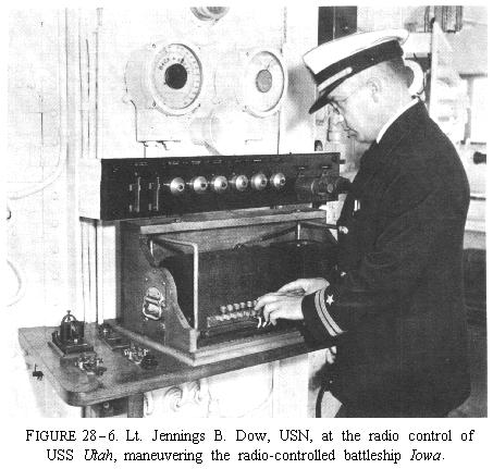
Following the war bitter arguments arose relative to the effect of aviation upon naval warfare. Many considered the day of the capital ship at an end. Aviation enthusiasts claimed that one bomb would sink a battleship. The Navy was willing and eager to support aviation but it desired that naval aviation be an integral part of the service, and that heavy ships not be scrapped without positive proof of the effects of bombings. Tests were arranged using captured German vessels and the obsolete U.S.S. Iowa. The first tests were for the purpose of determining accuracy; therefore the ships used as targets were anchored and concrete bombs were used.
In the final test, the Iowa was to be utilized as a maneuvered target and live bombs were to be used. Mr. John Hays Hammond, Jr., graciously consented to the use of his radio control patents for this purpose. Equipment was designed, built, and installed in the Iowa and Ohio by the General Electric Co. assisted by naval radio engineers. The Ohio was used as the control ship. On 21 June 1921 over 100 radio control signals were transmitted by the Ohio, from a distance of 8,000 yards, all of which functioned. At 0900, June, the crew was removed from the Iowa. At 0917 the target was placed under radio control but 3 minutes later the machinery in the engine and fire rooms ceased functioning. The crew returned and discovered trouble in the automatic boiler feed-water regulator. Shortly thereafter the arrival of the bombing aircraft was reported, necessitating the removal of the crew before the regulator could be properly adjusted. During the bombing 88 radio control signals were made, all of which functioned. Two direct hits were made on the forecastle of the Iowa which did exceedingly little damage.39 Battleships were not yet doomed.
The use of the Ohio for experimental purposes was curtailed by its use as a control ship but as soon as this duty was completed Mennerati resumed his assigned tasks. Unfortunately this work was terminated by the scrapping of the Ohio as a result of the Washington Disarmament Conference. She was placed out of commission early in 1922 and thereafter service tests and experiments were necessarily conducted on operating ships.
16. UNDERWATER PILOT CABLE
The loss of time of transports and cargo carriers caused by lack of visibility was one of the serious problems encountered during World War I. At the end of hostilities direction finder stations were being hastily erected at the entrances to important ports. These would suffice to get ships to the entrances but were of only slight value in navigating the restricted waters of the various ports.
Radio Aid E. C. Hanson developed and patented an audio-piloting cable. He authorized the Navy to utilize this patent without cost. Late in 1919 a system was laid in Ambrose Channel, at the entrance to the harbor of the city of New York, from Fort Hamilton, N.Y., out to the center of the channel, using lead and armored cable. From this point rubber-covered cable was laid and anchored in the center of the channel to its seaward beginning and thence to a point near the Ambrose Channel Lighthouse. This cable, the total length of which was approximately 14 miles, was energized by a 1-kw., 500-cycle generator. The flow of current in it was interrupted by means of an automatic transmitter which sent the code equivalent of "NAVY."40
The receiving equipment required by a ship utilizing the cable consisted of two coils wound with 400 turns of No. 24 copper magnet wire, each having the same values of resistance and inductance.41 These were placed over the side of the ship at about the waterline where they picked up the magnetic field created about the rubber-covered cable when it was energized. Each of these coils was connected to a separate vacuum tube amplifier. By means of a two-way switch the operator merely listened to first one coil and then the other and by determination of a signal strength estimated his location relative to the cable.
Official demonstrations were held from 6 to October aboard the U.S.S. Semmes, which used the cable entirely for controlling its position. The system was explained to the officials of various shipping interests, pilots associations, and other interested parties. These tests proved its possibilities as a means of permitting navigation in restricted waters during periods of low visibility.
Following the tests the project was transferred to the Department of Commerce, which by law was responsible for navigational aids. That Department evinced no interest in the project. The cable was removed from the channel and installed parallel to a landing strip and out into the Anacostia River at the U.S. Naval Air Station, Anacostia, D.C., for the purpose of testing it as an aircraft approach system.
This did not prove too successful because it required large loops on each wing of a plane and even with those the signals could not be received at altitudes much in excess of 200 feet. It was the first experiment with an aircraft instrument landing system.42
___________________
1 David Saville Muzzey, "A History of Our Country" (Ginn and Co., Boston, 1943), p. 776.
2 T. Johnson, Jr., "Naval Radio Tube Transmitters," Proceedings of the Institute of Radio Engineers, 1921, vol. 9, no. 5, p. 381.
3 E. C. Raguet, "Plate-Voltage Supply for Naval Vacuum-Tube Transmitters," Proceedings of The Institute of Radio Engineers, 1930, vol. 18, no. 1, p. 49.
4 Ibid.
5 A. Hoyt Taylor, "Radio Reminiscences: A Half Century" (U.S. Naval Research Laboratory Report, Washington, 1948), p. 156.
6 Ibid., pp. 158, 159.
7 Ibid., p. 161.
8 These transmitters and their normal usages are listed in Appendix M.
9 "Radioana," Massachusetts Institute of Technology, Cambridge, Mass., S. C. Hooper, undated memorandum, SRM 100-286.
10 Bureau of Engineering Monthly Report on Radio and Sound, May 1920.
11 "Radioana," op. cit., SRM 100 286.
12 Bureau of Engineering Monthly Report on Radio and Sound, April 1921.
13 Ibid., September 1921.
14 Ibid., December 1921.
15 Ibid., April 1922.
16 Ibid., July 1922.
17 These transmitters and their normal usages are listed in app. M.
18 Muzzey, op. cit., pp. 775-776.
19 "Radioana," op. cit.
20 Bureau of Engineering Monthly Report on Radio and Sound, March 1926.
21 Raguet, op. cit., p. 50.
22 The acceptor-rejector circuit is described in app. M.
23 Hammond and Purington "Some Foundations of Modern Technology," Proceedings of the Institute of Radio Engineers, vol. 45, no. 9, Sept. 1957, pp. 1194-1195.
24 Bureau of Engineering Monthly Report of Radio and Sound, July 1920.
25 U.S. Navy "Manual of Engineering Instructions," Government Printing Office, Washington, 1921, pp. 31-155, 31-157.
26 Taylor, op. cit., p. 182.
27 Ibid., p. 183.
28 Taylor, op. cit., pp. 186-187.
29 Taylor, op. cit., pp. 138-139.
30 Ibid., p. 197.
31 Ibid., p. 198.
32 Ibid., p. 199.
33 Ibid., p. 200.
34 "Radioana," op. cit., Clark, "Radio in War and Peace," pp. 275-303.
35 Bureau of Engineering Monthly Report on Radio and Sound, November 1920.
36 Bureau of Engineering Monthly Report on Radio and Sound, May 1920.
37 Ibid.
38 Ibid., 1920-1921.
39 Ibid., July 1921.
40 Bureau of Engineering Monthly Report of Radio and Sound, November 1919.
41 The Wireless Age, October 1920, p. 8.
42 C. Hooper "History of Radio, Radar and Sound in the U.S. Navy," Office of Naval History, Washington, D.C., recordings 48R115-123.
TOC | Previous Section: Chapter XXVII | Next Section: Chapter XXIX