Manual of Wireless Telegraphy, A. Frederick Collins, 1906, pages 97-99:

Wiring Diagram of a Complete Clark Transmitter.--For the Army the apparatus is made as compact and portable as possible so that it may be transported on the backs of mules or if necessary may be carried by men. The transmitter shown in Fig. 55 is one form of the apparatus used. The transmitter comprises three units or cases containing the apparatus besides the storage battery, aerial wire, and kites. The cases are made of oak and are provided with strong shoulder straps for carrying them. The first case contains the induction coil, and its dimensions are 8½ inches in height, 21 inches in length, and 8½ inches in width; it weighs 60 pounds. The second case contains the key, interruptor, etc.; this case is arranged to fold back and allow ready access to the operating parts. The outside measurements are 8 inches in height, 16 inches in length, and 9½ inches in width, while its weight is 30 pounds. The third case contains two half-gallon Leyden-jars carefully mounted within it, a step-up transformer, and inductance oil with the aerial switch and ground-plug connections. These are arranged in the top of the case, which is divided into compartments, with a shelf, the latter being used to support the rear part of the case for the step-up transformer and inductance coil. This coil is supported on hard-rubber pillars placed in sockets at the bottom of case. Its size is as follows: 15½ inches in height, 20½ inches in length, and 73/4 inches in width, the whole weighing 20 pounds. The figure represents the top elevation of the apparatus, the only connections shown being those exposed when the cases are open and those connecting the different cases. The storage battery is connected with the binding posts, marked "Line," of the case containing the key and interruptor; from the binding posts of this case, marked "Coil," these devices are connected to the binding posts of the primary of the induction coil. From the standards supporting the spark-gap balls a high-tension circuit is formed by connecting one side to the inner coatings of the pair of Leyden-jars and the opposite side of the spark-gap to the binding post of the case containing the step-up transformer and inductance coil, marked P. The outer coatings of the Leyden-jars are connected to the binding post marked P'. From this case the terminal marked S leads to one side of the aerial switch, and the opposite terminal, marked S', leads to earth.
Pages 116-117:
Diagram of a Clark Portable Receptor for Field Work.--This set is used to a considerable extent in the Army. It consists of an oak case enclosed in a weatherproof canvas bag strapped down and provided with a heavy leather handle for carrying. It is not necessary to remove the oak case from the canvas bag to receive, though where possible it is better to do so. The receiver-case is divided into two parts, namely, the case itself and the top or cover. The top is held down by two catches on the sides, and fastened at the back by a pair of hinges. On the top of the cover all the receiving instruments are mounted and wired on the under side, so that the wiring is all concealed. This receptor is provided with a simple microphone detector, or auto-coherer, the conductor-plugs of which are made of steel and the granules in the pocket, of carbon. This is mounted in a pair of standards supported on a hard-rubber base, and is connected in series with a pair of head telephone receivers.
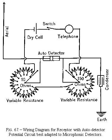
This receptor set is supplied with a call bell having an ordinary coherer and a relay, and the connections are so made that by inserting a plug in the circuit the filings, coherer, and relay are cut out, and when the plug is withdrawn from the spring-jack the filings, coherer, and relay are cut in. Diagrams of the connections are shown in Figs. 66 and 67, the first representing a wiring diagram for a shunt-circuit receptor, and the second for a potential-circuit receptor. The aerial wire may be connected plain as shown, or, better, through a tuning inductance coil. These diagrams may also be used with the Massie microphonic, Fessenden electrolytic, de Forest responder and other auto detectors. The shunt diagram shown in Fig. 66 is best adapted for microphonic coherers, and the potential diagram in Fig. 67 for electrolytic and other types of detectors.
Pages 177-179:

The Clark Portable System.--This is the portable system described in previous chapters. It was designed by Mr. Thomas E. Clark and is manufactured by the Clark Engineering Company of Detroit, Michigan. Many sets have been purchased by the Signal Corps of the United States Army, and it is used to some extent in the United States Navy.


