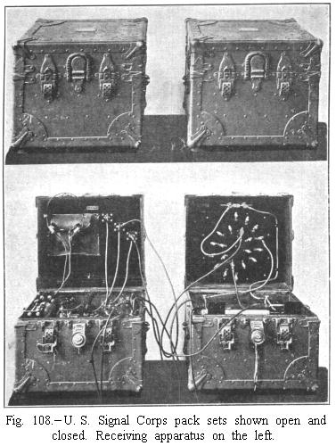
Drill Regulations for Field Companies of the Signal Corps (Provisional), 1911, pages 180-189 (Photographs are from the 1912 edition of Alfred P. Morgan's Wireless Telegraphy and Telephony Simply Explained):

Field  Wireless  Telegraphy--General  Principles.


    584. Wireless telegraphy will be used when distance, the character of the service, and the nature of the terrain prevents the laying of wire lines. This is particularly the case in service with the cavalry. It may also be used to keep parallel columns in communication on the march, and possibly to intercept messages sent by the enemy or to interfere with the operation of his wireless station.
    The locality for the station will be selected with as much care as the conditions permit. Open ground as far back from hills as practicable is to be preferred. The nearer to the commanding officer or his headquarters the headquarters station is placed the better. The range of the present pack set is from 15 to 20 miles.

General  Description  of  Pack  Wireless  Set.

[1910 type.]

    585. The set consists of:
          (1)  Two chests containing general operating apparatus.
(2)  A jointed hollow wooden mast of seven sections, and one extra section.
(3)  An antenna system of four three-ply stranded wires terminating in ropes, and a stranded lead wire fastened to a top insulator.
(4)  A rubber-covered wire counterpoise of four wires.
(5)  A hand-power generator.
(6)  Two storage batteries (four cells each).
(7)  A set of pack frames and leather bags fitting over the aparejos of the three mules that carry the equipment; (1) goes on one mule, (2), (3), and (4) on another, and (5) on another. When carried, (6) is put in two boxes that hook on the generator frame (5).

Transmitting  and  Receiving  Apparatus.
Fig. 107
    586. In one of the chests is contained the induction coil, the Leyden-tube secondary condenser, and the spark gap.
    587. In the other chest is placed the interrupter, key, primary condenser (under the base), the detector, and small receiving condenser in the box under the detector, and a tuning coil with sliding contacts. A spiral linking coil, small lamp, and connections for antenna and counterpoise are attached to the lid.
    588. Forty-foot mast equipment: Seven sections of the 5½-foot length tubular mast are used, four of the larger at the bottom and three of the smaller at the top. The tube is permanently fixed in one end of each section, except the top one, making the section and the tube practically one piece, and this facilitates very much quick handling of the mast. A large glass, porcelain, or composition insulator is screwed on the bottom section, and is used at the bottom of the mast to insulate it from the ground.
    589. Antenna: Four phosphor-bronze antenna wires are used, each 85 feet long. These wires are made up of three of the regular antenna wires plaited together. This gives more surface in the antenna, and prevents kinking. The guy ropes on the end of the antenna wires are 75 feet long and are insulated from the wire by four hard-rubber insulators placed in series. The antenna wires are secured to a metal piece on the insulator at the top of the mast. The lead wire, which is made up exactly like the antenna wires, is also fastened to this metal piece.
    590. Counterpoise: The counterpoise consists of four pieces of cable core (seven-strand No. 20 copper wire, eight thirty-seconds to nine thirty-seconds rubber insulation) 100 feet long. These four wires are soldered together at the inner end, the outer ends being insulated. At the junction of the counterpoise wires a lead wire of this cable core is also soldered for connection with the instruments and this joint insulated with pure rubber or okonite tape.
    591. The pack set should be insulated from the ground. Pins and spare parts should be placed near the base of the mast, so they will not be lost. The antenna is reeled up from outer ends by revolving the carriers. The counterpoise is reeled up from the center, the men drawing in the insulated wires and coiling them over the arm and hand. These precautions will prevent kinking the antenna and counterpoise wires. The steel joining tubes of the mast must be kept bright and well oiled.
    591. Each member of the section will thoroughly familiarize himself with his particular duties. At the same time each member of the section will be given instruction in the various duties in putting up the mast.
    592. To call a station, first listen in, and adjust detector and tuning coil to prevent interference. Then signal its call letter, signing your own call letter at intervals. In opening station the call will not be continuous, but will be at intervals of about three minutes, in order to give the other station a chance to answer. As soon as communication is established report to the signal officer. Firmly made distinct signals are especially necessary in wireless operation. Speed should be moderate, and no increase is to be made unless receiving is readily done. When difficulties exist, it is safer and, in the end, more expeditious to repeat all messages at least once.
    593. The sign "33" will be made when through sending, which means that you are going to switch over to the receiving side and listen in. Always change over from the sending side to the receiving side as quickly as possible, and adjust detector by means of the small buzzer furnished. When changing from the receiving side to the sending side always make several periods before commencing your message, in order to give the other station time to change over and get tuned.
    594. It is generally useless and always dangerous to attempt to operate in a thunderstorm. Therefore in general during such a storm it is advisable to connect the antenna direct to the ground.
    595. A wireless-telegraph operator must not only be able to send and receive messages, but must be familiar with the apparatus employed, in order to tune, adjust, overhaul, and make repairs. Wireless sections will have permanent call letters assigned. An accurate record of messages will be kept at each station, numbering them consecutively.

Instructions  for  Operating  Field  Wireless  Pack  Sets.
Plate 27
    596. The diagram of circuits and arrangement is given in plate 27.
    The various operations in sending and receiving are as follows:
    In sending, the control switch is thrown to the right. The current from the generator or storage battery then starts the interrupter, coming in at A, to B through interrupter magnets C, to interrupter driving contact screw D, through small interrupter spring to vibrator K, to E, 1, over to control switch through F, and back to battery through G. This causes interrupter to vibrate continuously, but the main current, controlled by the key, is not yet on. When key is closed the main current goes on as follows: From A to B through primary of induction coil to 1, through key and up to J and to large vibrator screw, through platinum point of this to large vibrator spring K, to E, to 1, to control switch, through F, and back to battery through G. The lower section of primary condenser shunts the contact points of the small vibrator through 4 and H on one side and through 1 and E on the other. The two upper sections shunt the contact points of the large vibrator and key through 1 and E on one side and through 2, 3, and I on the other. The rapidly interrupted current in the primary coil induces high voltage impulses in the secondary. The Leyden tubes, connected in parallel, are joined across this secondary at L and M. Being charged at each interruption they discharge through the circuit formed by the spark gap and included turns of the linking coil, producing at each discharge the high frequency oscillations in the included turns in the linking coil. These induce the high frequency oscillations in the turns of the linking coil included between the antenna and ground connections. These currents go to ground or counterpoise from the linking coil, down to N on the control switch, and to ground through "Gr." Those to the antenna go directly to "Ant."
    In receiving, the control switch is thrown to the left. The high frequency currents induced in the antenna by the waves from the distant station come in at "Ant." to control switch at O, to adjustable slider P on tuning coil, out at Q, through switch at R, and to detector at S, through detector, and up to "Rec. condenser," through this to T on the switch, and up to ground at "Gr." The telephone receiver shunts the condenser, including in its circuit the points U V of the potentiometer and the turns W Q of the tuning coil. The silicon or "Perikon" detector tends to rectify the high frequency currents. These, traversing the telephone receiver circuit, give the signals by causing vibrations of the diaphragm of the same acoustic frequency as the groups of waves corresponding to the interruptions or half periods in the primary of the induction coil or transformer.
    By closing the small battery switch shown at the bottom of plate 27 we impart to the telephone receiver circuit, through the points U V, a portion of the voltage applied at the terminals of the potentiometer.

Sending  Apparatus.

    Power: Either of two sources of power may be used. Storage batteries and hand-driven dynamos.
    Hand Generator: When hand driven power is used, it should be steadily applied. Owing to resistance going off and on when operating the key, care should be taken to work handles with arms somewhat stiffened, so as to resist sudden increases in velocity. Such changes are apt to strain the interrupter or cause trouble with the primary condenser. A storage battery connected across the hand generator will do much to assist in smoothing the action. One of 16 volts and quite small capacity will serve. The connection should be made while dynamo is being slowly turned, and disconnected when through sending, otherwise the battery will be run down by driving the dynamo as a motor. The hand generator requires frequent cleaning and occasional oiling. If it fails to "pick up" when the handles are turned, it may be it is being turned in the wrong direction. If it still fails when turned in the reverse direction, the commutator and carbon brushes probably need cleaning, and, possibly, adjusting. Steady operation of the hand generator is desirable to prevent, on the one hand, too violent action of the interrupter and flaming, or, on the other hand, insufficient voltage to give a good spark.
    Batteries: The most satisfactory used so far are the "Duro" dry-type storage. They should always be charged fully as soon as possible after receipt, at the rate of about 2 amperes. When standing they should have a setting-up charge at least once a month.
    They have approximately 20 ampere hours' capacity, and, when freshly charged, will serve for about eight hours' continuous sending. They should never be permitted to stand long discharged. For transportation the soft-rubber stoppers should always be placed in the cells. Keep the rubber stoppers out during the charge and put in a spoonful of water.
    Interrupter: The small contact should be screwed in until it just touches the spring, and will start when switch is placed at "send" position. Adjust until an amplitude of vibration of about one-half inch is reached, and then screw up small set screw on the side.
    The large contact should be adjusted so that the large platinum tipped screw pushes in the spring contact about one-sixteenth inch. If the large contact sticks or flames up when key is depressed, it may be that it is screwed in too far or has been roughened by previous burning. In the latter case the platinum contacts should be sparingly dressed with a smooth file. Continued and violent flaming indicates an open circuit in the condenser shunting the interrupter or the connections therewith. Violent sparking at the key and none at spark gap indicates a short circuit in the condenser.
    Key: Should be worked with a play of not less than three thirty-seconds inch. There is a tendency for it to stick, and this should be met by grasping the knob and working with an upward as well as downward stroke. When the interrupter sticks or flames badly the key should not be touched until interrupter is adjusted.
    Control Switch: The sending position is to the right, the receiving to the left.
    Spark Gap: Should in no case exceed one-quarter inch spark length. Between this and three-sixteenths inch gives the best effects. In the double spark gap each space should be about one-eighth inch. The spark should appear white and with some volume and give a sharp crackling sound. A hissing sound usually indicates that the spark is too short.
    Linking Coil: This is a flat spiral of rubber-covered wire with binding posts connected every half turn. These are numbered from 1 to 20, the adjoining half turns being connected to consecutive odd and even numbers.
    Two high-frequency (oscillating) circuits are connected with the linking coil. The first, called the "closed oscillating" circuit, includes the spark gap and Leyden eight-tube condenser. The two spring clips leading from these can include one or more turns of the linking coil.
    The "open oscillating" circuit leads at one side into the antenna connection, and at the other side to the binding post connected with the counterpoise wires. The clips from these are connected with one or more turns of the linking coil, and these may or may not include the turns already in the closed osciliating circuit.
    When there are turns common to the closed and open oscillating circuits, the coupling is said to be "close," and when not the coupling is said to be "loose." To place the closed and open oscillating circuits in "tune" with each other, the small glow lamp in the hard-rubber socket should be connected in the wire leading to the antenna post. The closed and open oscillating circuits are then tried on various adjustments until the glow of the lamp is brightest.
    On the linking coil it is advisable to start out with the closed oscillating circuit connected with 20 and 15, and the open oscillating clips connected with 20 and 14. Too many turns in the closed oscillating circuit are apt to make the spark ragged and red, and to cause flaming at the interrupter.

Receiving  Apparatus.

    597. Buzzer adjustment of the detector: A small commercial-type buzzer is connected with a dry cell and push button, and a wire from the buzzer connected to a bar of the receiving tuning coil. When the button is pushed and the buzzer operated, if the detector is in proper adjustment for receiving signals, the sound of the buzzer will be heard quite plainly in the telephone receiver when the wire is touched to the tuning coil.
    Silicon detector: This is the detector usually furnished with pack sets.
    In adjusting the detector:
    1. Adjust the pressure of contact point by gently pressing the spring sleeve down on the cup contact until maximum response is obtained in the telephone receiver.
    2. After clamping the sleeve in above position by the side screw, then slide the cup contact about to determine if the response can be improved. A very slight movement or tap will sometimes cause a great improvement in sensitiveness.
    It is important in this detector that both the rounded contact point and the upper or polished surface of the cup contact be kept absolutely clean.
    In case the rounded contact point becomes oxidized or otherwise tarnished, it should be cleaned by rubbing gently with very fine emery paper.
    The upper or polished surface of the cup contact can be cleaned by rubbing with a piece of soft cloth, or, better, wiped with a clean cloth moistened with carbon bisulphide.
    Under no circumstances rub the silicon with emery paper, as it will destroy the smooth surface.
    In damp weather or in tropical climates, where a film of moisture tends to form on the polished surface of the cup contact, a layer of insulating oil, such as paraffin, may be spread on the surface. This will in no way affect the operation or adjustment of the detector, as the pressure of the contact point readily displaces the oil layer at the point of contact.
    Perikon detector: This is used in a way similar to the silicon detector. The red crystals are quite friable, and in no case must the two contacts be rotated when in contact, as this would destroy the crystalline points.
    A slight motion or tap will often bring out the signals clearly, especially at the beginning.
    In both silicon and perikon detectors the battery must be connected in proper direction. In silicon, the positive is connected with the base, and with perikon to the metallic crystal side. The battery is not needed at moderate distances, but it improves the strength of signals when they come in faintly. In later types the battery circuit has been dispensed with.

In  General.

    598. Connections from the aerial circuit and counterpoise wires should not have any open loops in them. If there is any slack, it should be lashed up flat without having open loops, which seriously affect accurate tuning.
    The conductor to the antenna should not come within several inches of the ground or counterpoise conductors. Particular care should be observed to have good clean connections in the storage-battery circuit.
    It is essential that all metal and hard rubber of instruments should be kept clean and free from dust.
Pages 89-95:
Figure 107

The  Pack  Wireless  Section.

    306. The pack wireless section is normally composed of 10 mounted men and 4 pack mules.
    307. The men, except the chief of section, are numbered from 1 to 9. The mules are designated, respectively, as the "generator mule," the "chest mule," the "mast mule," and the "kit mule." Each mule is led by one of the men, and the section is formed in column of twos, the led mules being considered as one of the set of twos.
    308. The chief of section is on the right of the leading two, composed of Nos. 1 and 2, No. 1 on the right. These are followed by Nos. 3 and 4, and then by Nos. 5, 6, 7, and 8, leading, respectively, the mules carrying the generator, the chests, the masts, and the kit in order from front to rear, the mules on the right. No. 9 rides in the rear, and it is his duty to observe the packs and to keep up any lagging mule.
    309. It is the duty of all men, so far as they may be able, in addition to leading their own mules, to urge forward the mule immediately in front.
    310. When the section is acting alone, the chief of section may go where his services are most needed.
    311. The section is maneuvered as prescribed for the company mounted, and by similar commands.
    312. When the section is acting alone, it may when necessary march in column of files, in which case each man leading a mule will ride in front of his mule.

To  Open  Station.

    313. 1. Open station, 2. DISMOUNT. At the command open station, Nos. 3, 4, and 9 ride left front into line on No. 2; No. 5 stands fast, and Nos. 6 and 7 lead their mules left front into line on No. 5; No. 8 leads his mule by the left front, in front of and opposite the center of the line of mounted men. At the command dismount, the section is dismounted and the chief of section and Nos. 1, 2, 3, 4, and 9 turn their horses over to No. 8, and proceed to unpack the mules (except the kit mule). Nos. 5, 6, and 7, holding their mules in position, move their horses out of the way. Nos. 1 and 2 unpack the generator, the chief of section and No. 9 the chests, and Nos. 3 and 4 the antenna bags and mast, which are placed on the ground in rear of their mules; Nos. 5, 6, and 7 then lead off their horses and mules and turn them over to No. 8. As soon as the mules are unpacked No. 2 removes the cover from the generator, Nos. 3 and 4 take the contents from the bags, No. 4 takes out the counterpoise and places the pins or pegs for anchoring the antenna on the ground in front of the chest, No. 3 fixes the insulator with antenna attached into the top joint of the mast which No. 1 holds on the ground in front of the chest; Nos. 1 and then unloop and straighten out the antenna cords, placing them on the ground. No. 9 will now step on the chest and hold the joint of the mast in position, while Nos. 1, 2, 3, and 4 take up the antenna reels and pins and run out the antenna in the directions indicated by the chief of section. As soon as the antenna and the rope attached have been unreeled, the antenna men face in the direction of the mast and watch the chief of section for signals. When the antenna is paid out, No. 9 will raise the mast hand over hand, the other sections being placed underneath by No. 7. While the mast is being raised Nos. 5 and 6 set up the generator or batteries and untie and pay out the counterpoise, securing its center to the generator or anything to hold it in place. Nos. 7 and 9 connect up the instrument chests and the generator or batteries.
    When the mast is up, the chief of section may command tie in, when the antenna men will secure the rope attached to the antenna to the pins which they will drive into the ground.
    As soon as the antenna is secured the antenna men will assist in laying out the counterpoise.
    314. The chief of section will then detail an operator, one or two messengers as needed, men to turn the generator, and guards to protect the antenna from being run into and injured. The latter will also see that the antenna pins and cord do not become insecure.

To  Close  Station.

    315. The station is closed, taken down, and packed in a similar manner at the command close station, each man handling and packing the same equipment as in unpacking and opening station. When the mules are packed and the men are all mounted, the chief of section commands fall in, when the normal formation in column is resumed.
    316. Each man, having a permanent assignment of duty, soon learns to do his part quickly, and after the men have become proficient in handling the equipment the entire operation of unpacking and opening station or packing and closing station may be effected by the command open (or close) station.