Radiotelegraphy (U.S. Signal Corps), October, 1916, pages 85-86:


RADIO  APPARATUS  IN  USE  IN  THE  SIGNAL  CORPS.

    The Signal Corps has installed 10 radio stations in Alaska, varying in size from 1 kilowatt at Petersburg, Wrangell, and Kotlik to 8 and 10 kilowatts at Fort Gibbon, Fort Egbert, Nulato, and Nome. Stations of from 3 to 5 kilowatts have been installed at St. Michael Circle, and Fairbanks.
    In the Philippines stations have been installed at Manila, Fort William McKinley, and in the coast defenses of Manila, including a set of 8 kilowatts at Corregidor.
    In the United States 1 or 2 kilowatt sets have been installed in several of the Coast Artillery districts; 1-kilowatt set at Fort Wood; 3-kilowatt set at Fort Riley; an 8-kilowatt set at Fort Sam Houston; sets of from 1 to 5 kilowatts on 14 transports and cable ships; and sets of from one-eighth to 2 kilowatts on the harbor boats assigned to Coast Artillery districts that have a shore station.
    All the Alaska and the Philippine stations except Corregidor have their generators driven by gasoline engines. The generators in the Artillery districts and on the harbor boats are nearly all driven by motors from local electric power. The Fort Wood station may be operated either from a gasoline engine or the local electric-light plant. The Fort Riley and Fort Leavenworth sets are operated directly from city power.
    Two types of portable field sets have been issued by the Signal Corps. The smaller size, known as a field radio pack set, is furnished to the Organized Militia as well as to the field companies, and is described on pages 104 to 127. The range of these sets under normal conditions is about 25 miles over land, but much greater over water. Thus one of the one-eighth kilowatt sets, with a 100-foot mast, at Habana has worked with the naval station at Key West, a distance of about 110 miles.
    The larger size of field sets, known as a wagon set, is described on pages 93 to 104. It is of 2-kilowatts output and is carried on a two-chest pintle wagon, one chest with the engine and generator and the other with the transmitting and the receiving apparatus. The range of these sets varies from 75 to 800 miles, depending on favorable weather conditions, time of day or night, character of the land between the sets, etc.
Pages 93-127:
FIELD  WAGON  SETS.

    The following are the general instructions for the operation and care of the Telefunken two-wagon 2-kilowatt set:

    Engine.--The engine supplied with this set is a water-cooled, single-cylinder gasoline engine with a normal speed of 1,500 R. P. M., and the same general directions as to care and operation which apply to water-cooled gasoline engines in general apply in this case, and the principal points are briefly as follows:
    Before starting make sure--
    1. That the water tank is full.
    2. That all bearings have been oiled.
    3. That the engine has sufficient lubricating oil by means of the stopcock on under part of crank case. If it drips when opened, there is sufficient oil.
    4. That there is sufficient gasoline in the tank as indicated by the gauge on the front of the tank.
    5. That the main switch of the generator is open.
    To start--
    1. Open gasoline feed cock.
    2. Prime carburetor by plunger on top.
    3. Set the governor control handle just above the crank) vertically, i. e. halfway across the scale.
    4. Set the spark-control lever on the magneto on bottom notch.
    5. Crank.
    After starting--
    1. Make sure that the fan is running.
    2. Close main switch.
    Speed: The speed, as indicated by the tachometer on the engine, is controlled by the position of the governor control handle (directly over the crank) and by the position of the spark-control lever on the magneto (at the right), and the best position of each for any particular speed is best and easily determined by experiment.
    To shut down temporarily--
    1. Open main switch of generator.
    2. Press button on front of magneto until engine stops.
    To shut down permanently--
    1. Same as above.
    2. Ditto.
    3. Turn off gasoline.
    4. In cold weather empty all water out of every part of cooling system by means of the cocks provided for that purpose. Figure 77
    Generator.--The alternating-current generator supplied with this set is of the inductor type with the field and armature winding stationary, and has therefore no brushes or sliding contacts of any kind. Its normal voltage is 85. The exciter is an ordinary low-voltage direct-current machine. The voltage of the alternating-current generator is varied by means of the rheostat in series with its field. The rheostat is located in the lower left-hand corner of the front part of the instrument wagon. The connections between the power wagon and the instrument wagon are made by means of a flexible armored four conductor cable having the sockets so arranged that the terminals can be inserted only in the proper manner, the circuits of the alternator, exciter, etc., being shown in figure 77.
    Transmitter and receiver.--The connections of both are clearly shown in the drawing and require no further description.
    To adjust the transmitter for any wave length within the range of the set proceed as follows, assuming that the desired wave length is 1,000 meters:
    1. If it is intended to send at full power, adjust the voltage of the generator by means of the slide rheostat (at the left) to about 85 volts.
    2. If it is intended to send at less than full power, short-circuit one or more of the gaps by means of the clips provided and at the same time reduce the generator voltage about 10 per cent per gap short-circuited.
    3. Set the primary variometer (at the left) at the wave length desired, viz, 1000.
    4. Put the aerial-coil plug (at the right) in hole No. 1, marked 680/1050, This adds sufficient inductance to the aerial to bring the final adjustment within range of the aerial variometer.
    5. Make the final adjustment with the aerial variometer (also on the right and on one side of the aerial coils) by turning it slowly up from zero until the ammeter in the aerial or ground circuit indicates a maximum.
    6. The transmitter is now adjusted for the most efficient production and radiation of the wave length selected when used with the aerial and counterpoise supplied with the set.
    Receiver.--To receive, close the large double-pole switch at the top of the receiver.
    The plug holes marked with Roman numbers (at the right on the receiver) are connected to taps on the aerial or primary coil. The wave range of this coil is approximately as follows, with a proper aerial:
Plug.Condenser switch at--
Short waves.Long waves.
 
  I
  II
  III
  IV
  V
  VI
Meters.    
260-400
310-510
370-730
540-1,060
Meters.    
500-600
640-910
900-1,410
1,270-2,150
1,860-3,080
2,700-4,000

    The turns on the detector or loose coupling coil are variable by means of the switch located on its top, the wave range for each tap being marked.
    Either of the two detectors can be used by means of the switch located between them.
    For receiving a signal of a known wave length the following procedure can be recommended:
    1. Use tight coupling.
    2. Plug in on the aerial coil.
    3. Set the switch on the detector coil at about "λ=500/1000."
    4. Turn the condenser very slowly over the entire scale.
    5. Change the plug on aerial coil and repeat No. 4. When signals are finally heard, the coupling and the position of the switch on the detector coil are varied until the best results are obtained.
    NOTE.--In some cases two combinations of the aerial plug and condenser give almost equally good results. The best one is that in which the larger part of the condenser is used with condenser switch at "short waves" and vice versa, with the condenser switch at "long waves." The aerial used with this set should have a capacity of 0.0011 mf and a natural period of 450 meters.
    The following detailed notes on the circuits and operation of the set have been found useful as a result of actual work in the field: Diagram 75

POWER  CIRCUITS.

    Referring to connection diagram 75, it is seen that D. C. leads marked 3 and 4 go to both receiving switches in series. It is therefore necessary to have the main switches of both receiving sets in the same position--that is, cut of--when sending, even though one receiving set may have no aerial wire connected to it. A flash due to the breaking of this D. C. circuit will be seen at the rotary switch if the receiving set is cut in before the engine is stopped. The large double-pole switch at the top of the receiver when closed so as to connect the receiver to the aerial and counterpoise automatically disconnects the sending side from the aerial and counterpoise. This feature is not indicated in the diagram of connections where the receiving set when cut in is apparently shunted by the sending set.

TRANSFORMER  PRIMARY  CIRCUIT.

    From A. C. lead No. 1 to the primary inductance, to the snap switch, to the ammeter, to the primary of the transformer, to the key, and via A. C. lead No. 2 back to the generator. The voltmeter is across the A. C. leads as shown. If the voltmeter shows voltage, but upon closing the key no spark takes place at the spark gap, the snap switch in the primary circuit is probably open.
    The voltage, as indicated by the voltmeter, must never be more than 85. If it is desired to change the generator frequency (and the pitch of the note emitted), in order to secure greater selectivity for the set when working in the presence of other sets having about the same generator frequency, the engine may be slowed down or speeded up, but the drop or rise in voltage incident thereto must be compensated for by a change in the generator rheostat, so that the voltage will be kept constant at 85 when using all the gaps of the spark gap. Any violation of this rule will cause a breakdown in the transformer.

HIGH-FREQUENCY  CIRCUITS--TRANSMITTER.

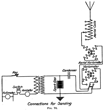
    Closed Oscillating circuit.This consists of the condenser, variometer, and spark gap. It is to be noted that the variometer is common to both closed and open oscillatory circuits, and, therefore, that changing the variometer (which is the one at the left-hand side of the chest and has scale divisions in wave lengths marked upon it) not only changes the period to which the closed oscillatory circuit is tuned, but also slightly changes the timing of the open oscillatory circuit. A word of caution should be given concerning the switch marked "Little" and "Great" which throws the coils of this variometer from a parallel to a series connection or vice versa. This switch can only be moved to the right or left--to "Little" or to "Great"--when the index is directly opposite the dividing line between the red and the white divisions. Any attempt to throw this switch when the variometer coils are in. any other position will only result in damage to the switch.

OPEN  OSCILLATORY  CIRCUIT.

    This consists of the aerial, aerial or loading coils, plug for cutting in proper coil, the aerial variometer (marked from zero to 180º), the variometer common to both closed and open oscillatory circuits, the hot-wire ammeter, and the counterpoise or ground.
    The antenna supplied by the Signal Corps for this set has a natural wave length of 450 meters and a capacity of about 0.0011 mf.
    It is found by experiment that the set using the Signal Corps 80-foot mast and rubber-covered counterpoise works best at about 1,000 meters, where the antenna hot-wire ammeter reads about 7¼ amperes.

CODING  OF  WAVE  LENGTHS.

    The great advantage of this set lies in the fact that any desired wave length from 675 to 2,220 meters can be sent out at will and if the wave length is changed after every word of a message, according to a prearranged code of wave lengths--for example, the first word sent with 700 meters, the next with 2,100, the next with 1,400, etc.--it will be difficult for any eavesdropping operator who has not the wave-length code to follow the changes of wave length with any success. Hence, messages may sometimes be kept confidential even when sent in plain English. This will take considerable drill on the part of two men, the operator and an assistant, who will rapidly make the necessary changes in the loading coils and variometers at a signal from the operator.
    The first step will be to make experimental determination of the combinations of loading coils and variometers necessary to produce the best radiation for every wave length within the range of the set and to set them down in the form of a table. Thus, starting with 700 meters, put the left-hand variometer at 700, put the plug in the hole marked 675-1,080, and then slowly move the aerial variometer from 0º toward 180º until the hot-wire ammeter shows the best reading. The various adjustments can then be noted in a table for future reference, thus: (The figures given are not the actual figures. These must be determined for each set separately.)
TABLE  I.
 
Wave
length.
Vario-
meter.
Loading
coil.
Aerial
variometer.
Amperes on
hot wire.
700
750
800
850
900
950
1,000
1,050
1,100
1,150
1,200
1,250
700
750
800
850
900
950
1,000
1,050
1,100
1,150
1,200
1,250
675-1,080
675-1,080
675-1,080
675-1,080
675-1,080
920-1,310
920-1,310
920-1,310
920-1,310
920-1,310
920-1,310
1,240-1,510
12
20
50
80
120
4
10
60
90
105
130
5
6.9  
6.95
7     
7.05
7.1  
7.15
7.25
7     
6.8  
6.6  
6.4  
6.2  

and so on, finding the best combination for every 50 meters increase in wave length up to the limit of the set.

LIMITATIONS  OF  SYSTEM  OF  CODING  WAVE  LENGTHS.

    It will be noted that there is one best wave for the set, namely, about 1,000 meters. From some experiments made recently at Fort Leavenworth it is concluded that it is safe to state that, up to about 75 miles over average land, the falling off of energy due to the use of the longest wave lengths will not be so great as to prevent the use of any wave length within the limits of the set (675-2,220 meters), but that beyond that distance, up to the extreme daylight distance of the set (about 185 miles), it would be safer not to work with any wave length greater than 1,800 meters.
    Only further experiments in the field, between two similar sets working at gradually increasing long ranges, will determine the greatest distance at which the whole scale of sending wave lengths may be used.
    From the table plotted as above, different codes of wave lengths, differing by many meters from each other, may be agreed upon, to be changed daily in actual work, and confided to all operators concerned. Figure 78

RECEIVING  CIRCUITS.

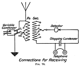
    Primary or aerial circuit.--One lead from aerial comes through combination switch to the primary of the transformer (shown on the left of fig. 78), from there through plug contact to a point on the little switch marked "Long waves"--"Short waves"; and, if the switch is thrown to the long-wave side, the circuit goes direct to the ground; the variable condenser being then in parallel with the primary of the transformer. If the switch is thrown to the short-wave side, the variable condenser is in series with the aerial, the primary of the receiving transformer, and the counterpoise or ground.
    The secondary or detector circuit consists of the secondary of the transformer in series with the usual stopping condenser, connected through the main switch to the detectors. The telephones are in shunt to the stopping condenser.
    The detector supplied is of the iron pyrites variety, which lacks the sensitiveness of the Perikon. Any other detector may easily be substituted for the detectors supplied with the set, the range of which may be thereby easily increased.
    With the switch thrown to "Long waves" the operator will get the best results when using a small number of degrees of the variable condenser and as large primary as possible, and, vice versa, with the switch to "Short waves," which places the variable condenser in series with the primary coils. The largest possible amount of capacity of the variable condenser and the smallest amount of primary inductance should be used for maximum strength of signals.
    The combination switch which is used primarily to cut the receiving set onto the antenna and counterpoise simultaneously performs several operations. Opening this switch disconnects the receiving set from the antenna and counterpoise; automatically connects sending set to the aerial and counterpoise; closes D. C. circuit of generator; disconnects detectors from secondary of receiving transformer, thus opening that circuit and preventing detectors from being affected by the spark when sending, and also opens the primary circuit of the receiving transformer. As the limits of the various coils of the primary and secondary are marked, there should be no difficulty about setting the receiving apparatus approximately for the wave length of a station whose wave length is known. The operator then varies his condenser, and also the coupling between the primary and secondary of the receiving transformer, until he gets the best adjustment. Changing the coupling (that is, pulling the secondary away from or pushing it closer to the primary) changes the wave length, though to not as great an extent as does varying the condenser. Some stations can not be heard at all well unless the secondary coil is pulled some distance away from the primary. Practice is the best guide to a working knowledge of the tuning of the receiving set. Figure 76
    Figure 76 shows simplified schematic diagram of the transmitting circuits. Figure 77 shows the generator circuits.

CALIBRATION  IN  WAVE  LENGTHS.

    The receiving set should be calibrated so as to locate the actual combinations necessary for receiving the wave lengths sent out by a similar sending set, either by actual tuning to another set sending out successive wave lengths differing from each other by 50 meters, as outlined above, or by using the wave meter provided with each wagon set as a sending device, and with its coupling coil held near the antenna lead, set up, consecutively, different wave lengths in the antenna and make adjustments of receiving set necessary to tune to the particular wave lengths sent out; then compile a table showing adjustments of condenser switch, primary, secondary, and variable condenser necessary for each wave length in turn, so that the receiving operator can at once adjust his receiving apparatus to any desired wave length, and, by quick changes, constantly follow, according to prearranged code the message sent out by the other station.
    It is recommended that, in order to eliminate one adjustment of the receiving set, the primary and secondary of the receiving transformer be kept in the same relative positions throughout; that is, as close to each other as possible. This, while possibly sacrificing efficiency, secures simplicity. The receiving operator's chart may be arranged as follows:
    Best receiving adjustments necessary to tune to wave lengths used by similar wagon-set sending wave lengths shown in Table I.
TABLE  II.
 
Wave
length.
Switch.Primary.SecondaryCondenser.
700
750
Short waves......
Long waves.......
370-730
640-910
500-1,000
500-1,000
80º
40º
    NOTE.--The condenser adjustments given above are not the actual ones necessary for wave lengths given.

And so forth for every 50 meters.
    Constant drill in changing sending and receiving adjustments, carried on between two or more similar sets, will result in remarkable efficiency and rapidity, and the time necessary for transmission of messages will be found to be but little increased over that required when sending on a single wave length.

RECEIVING  BY  CODING  OF  WAVE  LENGTHS.

    Two complete receiving sets are provided with each wagon set, though ordinarily only one is used. Two messages from different stations may be copied from the same antenna without either operator hearing the message copied by the other. To do this it is, of course, necessary to have a lead from the aerial running to each of the receiving sets. A change in the tuning of one receiving set will call for a slight readjustment of the other receiving set, however, in order that the latter set may stay in tune with the given wave length.
    The use of two receiving sets in parallel makes it comparatively simple to follow a message sent according to a prearranged code of wave lengths, for it is perfectly practicable to so arrange the wave-length code that the waves of any length within certain limits will fall within the limits of the condenser of either one set or the other, and either one operator or the other, without making any change of adjustment other than a mere movement of the condenser handle, will have his apparatus constantly in resonance with the incoming waves.
    Thus, let us say that in the code agreed upon, which includes all wave lengths between 900 and 2,150 meters, the first word will be sent with a 900-meter wave, the next with 2,100, followed by 1,500, 1,850, 1,050, 2,000, etc.
    The two sets are cut in at the receiving station and are each manned by an operator. Operator No. 1, at the left, puts the plug in the hole of the primary of his receiving set marked "900-1410," couples his primary and secondary as closely as possible, throws his receiving switch to "Long waves," and puts the switch of the detector coil on whatever coil will give him the strongest signals. He can then, by merely moving his condenser from 0º toward 180º, tune his set to any desired wave between 900 and 1,410 meters, and it will be his duty to copy all words of the message which may fall within those limits.
    Operator No. 2, on the right, similarly throws his switch to "Long waves" and plugs in primary coil marked "1270-2150," and makes the other adjustments as given for No. 1. He is then ready to receive any wave between 1,270 and 2,150 meters by merely setting the pointer of his condenser at the proper number of degrees on the condenser.
    From Table II, prepared as before described, either operator can set his condenser accurately and instantly to the proper reading for any desired wave length within limits; hence when the message is to be received the first word sent as per schedule 900 meters is copied by No. 1 operator, who has his pointer at the proper place on the condenser scale; the second word at 2,100 meters by No. 2, who has already set his pointer at the proper place. As the third word is sent at 1,500 meters, No. 2 readjusts his condenser for the next word, and later turns the pointer to the proper place for the next word at 1,850; then No. 1 comes in on his set and copies the next word at 1,050 meters, No. 2 the next at 2,000, and so forth, the words being placed together in accordance with the order of their receipt so as to make a complete message.
    This method of using two operators saves time by dispensing with a number of switch and plug changes, which a single operator would have to make in using only one receiving set.
    The method of using two receiving sets tuned as above could easily be worked by one operator who could wear the single head receiver of one set on one ear and that of the other on his other ear.
    All these methods should be practiced continually to improve the skill of the operators.
    Care must be taken to close or open both main switches of the receiving set at the same time when working both receiving sets in order to prevent sending into one of the receiving sets and burning it out.

FIELD  RADIO  PACK  SETS.

    The smaller size of portable sets, known as a field radio pack set, has been made in several models designated by the number of the year in which they were made. Owing to the rapid improvement in design and construction, the 1912 model has become practically obsolete.

1913  MODEL.

    Radio pack set, model 1913, consists of the following units:

1 operating chest.
1 hand generator.
1 mast.
1 pack frames, set (3 frames).
1 tent.

    Each unit contains component parts as follows:

Operating chest:
      1 chest.
      1 resonance transformer.
      1 condenser.
      1 oscillation transformer.
      1 sending key.
      1 spark gap.
      1 hot-wire ammeter.
      1 switch.
      1 receiving set.
      1 connecting cord for generator (4-conductor, with plugs).
      1 connecting cord, with plug, for antenna.
      1 double-head receiver.
      1 test buzzer.
      1 tool kit.
      1 extra section for transformer secondary.
      1 extra set crystals.
      1 canvas case for receiver.
      1 connector, 4-wire (lower half), generator.
      2 connectors, 2-wire (lower half), antenna and counterpoise.
      1 copy "Radiotelegraphy."
Hand generator:
      1 generator.
      2 cranks.
      1 stand.
      1 speedometer (carried in operating chest).
      1 cap for speedometer opening.
      1 canvas hoed.
Mast, type F. (Type D mast has 1 top, 1 bottom, 5 intermediate, and 3 extra sections)
      1 top section.
      1 bottom section.
      8 intermediate sections.
      4 intermediate sections, extra (3 for tent).
      1 antenna.
      1 counterpoise.
      9 carriers, wire.
      4 pins, antenna.
      2 hammers.
      1 set adapters for tent (4 pieces).
      1 bag, antenna and counterpoise.
      1 bag, accessories.
Pack frames, set:
      3 frames (1 set). Each frame is complete with cincha, 2 cincha straps with rings and snap hooks, and 2 straps with snap hooks at each end.
Tent:
      1 tent.
      14 pins.
      2 guy ropes.
      1 insulating device.
Fig. 81/82 (a)
Fig. 81/82 (b)
Fig. 81/82 (c)
    Complete sets should be designated as "radio pack sets, complete," giving year and serial number, and should be so carried on property returns, invoices, and shipping manifests.
    Incomplete sets should not be so designated, but units in them which are complete should be designated as under the unit heading above and units that are not complete should be designated as under the component part heading. When units or component parts are used to complete sets they should be expended.
    Operating chests and hand generators should always be designated by the year and serial number, and masts by the type letters.

SECTIONAL  MAST.

    The new type F sectional mast with short sections is superseding the type D with long sections as the stock of the latter becomes exhausted, as it has been found by experience that a mast with short sections can be raised more easily from the ground than one with long sections. The type F mast equipment consists of 14 sections, each 4 feet 2 inches long or 5 feet 2 inches over all, including the coupling tube. The 10 sections are used for the mast itself, 3 sections for the shelter tent when erected, and 1 extra section for use in case one of the others becomes unserviceable.
    When starting to erect the mast, the four antenna wires and guys should be laid out on the ground at right angles to each other and the umbrella insulator put on the upper end of the section that is not provided with a coupling tube. This section should then be raised and eight more sections with coupling tubes added, section by section, the tenth and last section being the one provided with the insulator fixed at the bottom end. During the erection the mast should be kept as nearly vertical as possible by the men holding the distant ends of the antenna guy ropes. Owing to the liability of the mast to buckle, no attempt should be made to erect the entire mast at one time; that is, by coupling all sections together and raising by means of the guys.

ANTENNA  AND  COUNTERPOISE.

    The standard antenna is of the umbrella type with four radiating wires, each 85 feet long, suitably insulated at the open ends and held as nearly horizontal as possible by guy rope extensions, each 85 feet long, the outer ends of which are made fast to ground pins. The standard counterpoise has four radiating insulated wires, each 100 feet long, laid out on the ground under the antenna wires. Both antenna and counterpoise wires are carried on hand reels for convenience in packing and quick reeling and unreeling in setting up and taking down the mast.

GENERATOR.

    The generator is a hand-driven, 18-pole, alternating-current machine having an intermittent output of 250 watts at 110 volts and 500 cycles at a speed of 3333 R. P. M. It is self-excited, the exciting current for the fields being generated by a small shunt-wound direct-current machine, the armature of which is mounted on the same shaft as the alternator armature. The exciter has two poles and delivers the direct current at about 110 to 150 volts. The whole machine is driven by two handles, which should be turned at the rate of 33 R. P. M. to give the necessary armature speed of 3333 R. P. M., the combination gear having a ratio of about 100 to 1. The direction of rotation of the handles must be as shown by the arrow on the top of the gear case, as otherwise the machine will not deliver any current. The whole is inclosed in a dust-proof aluminum case. To obtain access to the commutator, remove the flywheel, taking care not to lose the key on the flywheel shaft; then remove the large brass nut and the aluminum disk held in place by the latter, after which it will be found that the commutator is readily accessible. To remove the armature from the machine, proceed as above; then take off the casing covering the spur gears at the opposite end of the shaft, and the gears themselves; before removing the armature take the brushes out of the holders to avoid injuring or breaking them.
    The tension on both sets of the generator brushes should be kept as light as possible consistent with good commutation. A small increase in the friction of these brushes will require considerable additional power to drive the machine. Both sets of brushes can be removed when necessary through openings in the lower part of the case, the D. C. exciter brushes being at the flywheel end and the A. C. brushes at the opposite end.
    A canvas cover is provided for the generator, which should be kcpt on at all times when the generator is not in use.

SPEED  INDICATOR.

    A speed indicator is mounted on the upper part of the gear case in sight of the men driving the machine so as to show if it is being driven at the proper speed, at which time the red line on the moving vane coincides with the black index or arrow at the window. The vane is divided diagonally into black and white parts, the white showing if the speed is too low and the black if too high.
    In putting the speed indicator in place it may be necessary to turn handles slightly so as to permit the gears to engage.
    In case the vane of the speed indicator comes on the underside when the indicator is screwed into place, it can be turned into proper position after loosening the depressed set screw on the threaded part fitting into the case and then tightening the set screw again.
    In making the set ready for transportation, the speed indicator should be removed and packed in its proper place in the operating chest and the opening closed with the brass plug provided.

GEARING.

    The gearing is a combination planetary worm-and-spur type of high efficiency when in proper alignment. The high-speed shafts have ball bearings and the gears run in grease or oil, so as to reduce the friction as much as possible. The gears should never be taken apart unless absolutely necessary to replace worn or broken parts, and then only by an experienced person. If not properly reassembled, or if the driving gear does not run perfectly true with the worm, undue friction and wear will result, the machine will be harder to turn than before, and the gears will be speedily destroyed.
    The gears and ball-bearings can be lubricated by either a non-fluid oil or a light, thin oil, such as Medium Monogram, but both must be free from acid and water to prevent rusting. If oil is used it should be supplied through a small cap on the opposite side of the case from the speed indicator. The level should be kept not more than one-eighth inch above the lower edge of the glass window at the flywheel end of the gear case; if kept above this, the oil will overflow to the lower part of the case and cause trouble and sparking at the commutator and collector rings. The same kind of oil should be used on the flywheel shaft through the small hole on the upper side of the bearing.
    If nonfluid oil is used it should be supplied through the opening where the speedometer is screwed into place. Not less than a pint nor more than a quart should be used in the main gear case, but only a small amount in the spur gear case at the end opposite the flywheel, as otherwise the machine will turn hard on account of choking the gears with too much nonfluid oil in the narrow gear case.
    With the exception of an occasional addition of oil, the machine should run for months without attention. If the oil becomes thick or dirty, the gearing should be washed out with gasoline and refilled with clean oil without dismantling.
    Care must be taken not to start or stop the machine suddenly, as this may strain or break the gears. The machine must not be stopped by means of the handles, but only by friction on the flywheel.

CONNECTIONS.

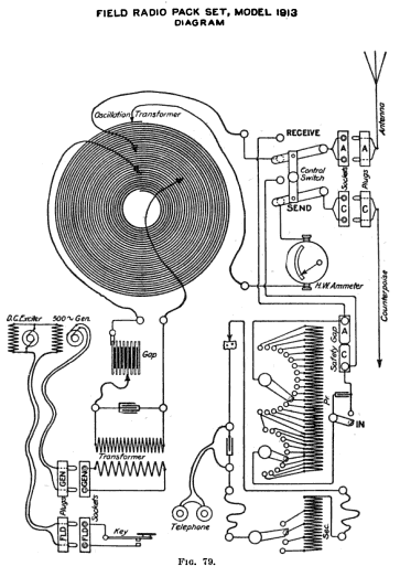
    The leads from the armature of the A. C. generator are directly connected to the transformer primary by means of the heavy pair of leads, the larger plug of which being put into the socket at the left-hand end of the operating chest marked "Gen." and the smaller plug into the socket on the underside of the gear case, also marked "Gen." The sending key is in the circuit of the alternator fields and the exciter armature, and is so connected by means of the light pair of leads, the larger plug of which being put into the socket at the left end of the chest marked "Fld." and the smaller plug into the socket on the underside of the case, also marked "Fld." By the use of these circuits, the electrical load on the machine is limited to the small one of the exciter field, except when the key is closed in sending. Experiments have shown that twice the output of the former machines can thus be obtained with practically no more tiring effects on the men than before. Figure 79

OPERATING  CHEST.

    In this chest is mounted the transmitting and receiving apparatus, the diagram of which is shown in figure 79. To put the chest in condition for sending, connect the double contact plugs of the leads from the hand generator, field, antenna, and counterpoise to the receptacles marked "Gen.," "Fld.," "A," and "C," respectively, and the four variable contact clips on the leads from the condenser, spark gap, antenna, and hot-wire ammeter, to the four points on the flat spiral, as indicated on the diagram, making sure that the counterpoise clip is at the end of the outside turn. Set the control switch at the "sending" or lower position. Release the indicating needle of the ammeter by turning the small knurled screw at the left-hand side of the upper binding post. When the needle is free, adjust to zero position on the scale by means of the small knurled screw at the right side of the upper binding post. Set the variable spark-gap contact on the fifth plate, counted from the left end, so as to put four gaps in circuit. Start the generator, and when the proper speed is obtained the set is ready for sending.

QUENCHED-SPARK  GAP.

    The spark gap used in this set is made up of several copper disks separated by mica washers about 0.01 inch thick. Its action is to allow all of the energy of the closed oscillating circuit to be transferred to the open or radiating circuit in a few oscillations, after which the spark is quenched and the circuit is, in effect, open. The activity in the closed circuit having ceased, the open or radiating circuit continues to oscillate at its own period, radiating waves of its own wave length without any retransfer of energy to the closed oscillating circuit, which continues to remain open until a spark breaks down the gap again at the peak of the next alternation.
    In order to work at maximum efficiency, the quenched-spark gap should be kept cool. It is for this reason that the plates are provided with thin cooling flanges having a large surface exposed to the air, and are blackened, a black body cooling more rapidly than one highly polished. If the gaps have become too hot, as by keeping the key closed for a long time, the antenna current will gradually decrease, the loss at times being as much as 40 per cent, so that it is always best to allow the gap to cool before using again.
    The gap should not be taken apart to clean its sparkling surfaces like an ordinary type of open gap. In general the more frequently such a gap is opened the more unsatisfactory may be its operation, The explanation is that the repeated opening of the gaps introduces air each time, and that with free exposure to air the sparking surfaces are corroded or pitted, but that when kept air-tight they are worn smooth and clean by the sparking action. Sometimes, if there is a flaw in one of the plates or if air leaks into the gap, there will be a noticeable drop in the antenna current, and the note will become poor. When it is believed that the trouble is confined to one or two gaps it is possible to continue sending without dismounting the whole gap by short-circuiting the bad gaps by means of clips provided for the purpose, in which case as many new gaps must be put into circuit by adjusting the movable clip to the right as were cut out by the short-circuiting clips.
    The gap should be dismounted only when the trouble has been located in the gap and it has been found impossible to remedy it by short-circuiting the different gaps in use. The gap should be dismounted only by an experienced man, who should clean the surfaces by rubbing them face down on fine emery cloth or paper on a flat surface. It is absolutely necessary that both the bearing surface and the sparking surface be kept true and plane, as shown by a straightedge.
    Great care should be exercised in reassembling the gap to set the mica washers accurately on the annular surfaces of the disk and to put on enough tension with the clamping screws to render all of the gap spaces air-tight.

TUNING  OF  SENDING  SET.

    The tuning of the closed and open circuits to resonance, and the determination of the correct coupling between them are the two most important adjustments in a quenched spark transmitter. In the present type of directly coupled set with a flat spiral as the oscillation transformer, these adjustments can be made either with or without the help of a wave meter. If made without the meter the adjustments are more difficult and must be found by trial, but they should satisfy the following tests: (1) The number of turns in the closed circuit should be chosen so as to give the desired wave length; (2) the antenna hot-wire ammeter should show the maximum reading that can be obtained by adjusting the number of turns in the open circuit according to the table on page 114; and (3) the note as heard in the telephones of the receiving set should be clear and characteristic of 500 cycles. These adjustments are, in general, dependent on each other, an incorrect change in one seriously affecting all the others; but when obtained the circuits will be in resonance at the desired wave length, they will be correctly coupled, and the closed-circuit condenser will be charged and discharged regularly once per alternation.
    The adjustments should be made as follows: Set the closed and open circuit clips on the turns corresponding to the desired wave length, as given on page 114. These turns are approximately correct with the standard antenna and should he used in beginning to make the adjustments. If the antenna ammeter reads between 2.2 and 3.0 amperes and the note is clear and of 500 cycles, then the adjustments are correct and the circuits properly tuned. If the ammeter reading is low and the note low and clear or low and ragged, possibly the circuits are correctly tuned, but there are too many gaps in circuit, and the condenser is being charged and discharged either regularly or irregularly only every second or third alternation. Reduce the number and see if this change gives a clear 500-cycle note, etc. Similarly if the note is high and hissing, the condenser is being charged and discharged more than once per alternation. Increase the number of gaps and see if this change gives a clear 500-cycle note, etc. If none of these changes gives the correct adjustments, then the circuits are not in resonance, or the coupling is wrong. Move one of the open-circuit clips to see if the correct adjustments can be obtained; it is impossible to state which clip should be moved or in which direction. If the change of one clip is not sufficient, move both open-circuit clips until, by repeated trials, the correct adjustments have been found. If possible, leave the counterpoise clip on or near the outside turn, so that it will be at ground potential. It will be found that the character of the note will be changed as these various changes in coupling and tuning are made, but the clearest 500-cycle note will be obtained when all adjustments are correct and the circuits properly tuned. After the adjustments have been completed at this wave length, tabulate the results as shown and repeat at other wave lengths within the range of the spiral.
    Although there is no direct test that can be applied, except with a wave meter, to determine if a single wave length is being radiated, yet in general this will be the case if the adjustments satisfy the tests as indicated on pages 110-111.
    If a wave meter is available the adjustments are much easier to make, and they should satisfy the following tests: (1) A single sharply defined wave should be radiated of the desired wave length, (2) the antenna ammeter and the signals in the telephones of the meter should show the maximum reading and signals obtainable under the first condition, and (3) the note should be clear and of 500 cycles.
    It will probably be best to use the wave meter with a detector or helium tube, as shown in figure 48, because it will be impossible to turn the hand generator at a sufficiently constant speed to obtain steady readings on the wattmeter and hence difficult to determine the resonance point and wave length.
    The adjustments for tuning should be made as follows: Disconnect the open-circuit clips and set the closed-circuit clips on the turns corresponding to the desired wave length as given on page 116. Measure the wave length according to the instructions on page 111 to make certain that it is correct. Set the open-circuit clips on the turns given in the table, and, with the wave meter near the antenna or counterpoise wires, but not near the spiral, see whether there is one or two wave lengths in the meter. If there is a single sharply defined wave length, and the antenna ammeter reading can not be increased by slight changes of either or both of the open-circuit clips and the note is clear and of 500 cycles, then the adjustments are correct and the circuits properly tuned. If there is only one wave length, but the antenna ammeter reading is low and can not be increased by slight changes in the open-circuit clips, then the coupling is too loose and must be tightened. Move the open-circuit turns in use inward as a whole, by moving both clips inward and slightly increasing the number of turns in circuit to allow for the decrease in their diameter, until with a single sharply defined wave length the antenna ammeter reading is a maximum, etc., as before, in which case the circuits are properly tuned. If the note is low, decrease the number of gaps; if high and hissing, increase the number as previously described. If, however, there are two wave lengths, move one or both of the open-circuit clips, but it is impossible as in the previous case to state which clip or in which direction, until by repeated trials it has been found that there is a single sharply defined wave length, a maximum antenna ammeter reading, etc., as before, in which case the circuits are properly tuned.
    After the adjustments have been completed at this wave length repeat at other wave lengths as before and tabulate the results as on page 114.
    If the one-eighth or one-fourth kilowatt motor-generator or the engine-driven one-fourth kilowatt generator supplied by the Signal Corps, is available, it should be used as the source of the 500-cycle current because its voltage will be much steadier than that of the hand generator. When the motor-generator set is used, the A. C. armature and the D. C. motor should be protected from "kickbacks" due to the use of the sending key in the alternator fields by two high-resistance carbon rods mounted on suitable bases to be connected as follows: The end terminals of one rod to the two A. C. leads close to the machine; the end terminals of the other rod to the two main line D. C. leads close to the machine, and the middle points of both rods to be connected together and this common point grounded on the frame of the machine. The constant speed of the motor generator makes it possible to get steady readings on the wattmeter of the wavemeter, and hence easy to find the resonance point and wave length. It may also be more convenient than a detector because it is often difficult to keep a detector point in sensitive adjustment on account of the nearness of the spark gap and to determine the resonance point on account of the continuous note in the telephone. However, the detector and helium tube can be used if desired; the circuits will be correctly tuned no matter what means are used for determining resonance. The circuits should be adjusted to resonance, etc., as described in previous paragraphs.
    In some cases it may be convenient to use the following slight modification of the method described on page 111. Disconnect the transformer secondary from the closed circuit and connect it to the two terminals of a small zinc or brass spark gap, one of which is connected to the counterpoise and the other to the standard antenna. Measure this wave length, which will be the fundamental wave length. Next insert, say, two turns of the spiral, Nos. 28 to 30, counting the turns from the inside turn outward, in series with the antenna, and measure this wave length. Continue in this manner until all wave lengths are measured within the range of the spiral and tabulate as shown on page 114. Next make the standard connections, setting the open-circuit clips on the turns corresponding to the desired wave length, as just obtained. Set the closed-circuit clips on the turns given in the table on page 116, and make the necessary adjustments by moving these clips until it has been found by trial with the wavemeter that there is a single sharply defined wave length, maximum current in the antenna, etc., as before. Tabulate these results and repeat for wave lengths within the range of spiral. In this case the closed circuit is tuned to the open circuit, whereas in the previous case the open circuit was tuned to the closed circuit but the same tuning points will be found for the same wave length, whichever method of tuning is used.
    It is impossible to use exactly the same method as on page 116, in which the number of turns for a given wave length is determined for both the primary and secondary circuits, after which the principal adjustment is one of coupling, because the number of turns in the primary circuit of the spiral at any wave length will depend on the part of the spiral which is included in the circuit, and hence it will vary with every combination of turns. It is for this reason that the primary tuning and coupling must both be found by trial.

OPEN-CIRCUIT  AND  CLOSED-CIRCUIT  TUNING.
 
Wave length.Antenna.Counterpoise.
Meters.
300
325
350
375
400
425
Turn No.
26 7/8
24 7/8
22 3/4
20 3/4
18 5/8
16 5/8
Turn No.
30
30
30
30
30
30

Turns to be counted from the inside turn outward.
 
Wave length.Closed-circuit
clips.
Open-circuit
clips.
Meters.
300
325
350
375
400
425
Turns.
8 and 12 1/2
8 and 13 1/8
8 and 13 5/8
8 and 14 1/8
8 and 14 5/8
8 and 15 1/8
Turns.
26 7/8 and 30
24 7/8 and 30
22 3/4 and 30
20 3/4 and 30
18 5/8 and 30
16 5/8 and 30

Turns counted from the inside turn outward.

    Although a transmitting set using the flat spiral oscillation transformer is not as easily tuned as some other types, yet when the adjustments have once been made and tabulated it is practically as efficient as other types. It has the advantage of being one of the simplest, most rugged, and compact forms which can be installed in a field set.

RECEIVING  SET,  TYPE  B.

    The receiving set consists of an inductively connected transformer with broadly tuned secondary circuits, as mentioned on page 73, galena, or other similar detector, high-resistance telephones, etc., provided with the necessary switches for tuning to different wave lengths. The primary circuit includes the antenna, primary coil, series condenser or not as may be needed, and counterpoise. The antenna is connected to the primary coil through switches which put into circuit a variable number of turns, steps of 10 turns being inserted by one dial switch and single turns by the other. The total number of primary turns is thus the sum of the numbers on the two dials indicated by the two switch arms, which can be varied by single turns from one to the whole number in the coil. For wave lengths shorter than the fundamental wave length of the antenna, a fixed condenser is inserted in series with the primary coil by throwing the switch near the binding post marked "G" to the position "In," as shown in figure 79. For the longer wave lengths the switch is thrown to the other position, short-circuiting the condenser, and thus leaving only the coil in circuit. The secondary circuit includes the secondary coil, detector, and the stopping condenser shunting the telephones. The coil is variable only by sections, marked "100," "200" etc., the smaller numbers to be used at the shorter wave lengths and the larger ones at the longer wave lengths. The position of the secondary coil within the primary--that is, the coupling--is variable, and for the sake of convenience a scale is provided so as to be able to note the different adjustments. The coupling is closest when the secondary is inside the primary, in which case the scale reading is 0, and vice versa, the coupling is loosest when the secondary is drawn outside the primary and the scale reading is 40.

SHORT  WAVES.

Primary condenser in series.

[Switch on "In" contact.]
 
Wave
length (in
meters).
Primary
turns.
Secondary
turns.
Coupling
scale.
200
300
400
500
600
700
800
Etc.
18
26
36
47
60
74
88
Etc.
100
200
200
300
300
400
400
Etc.
20
20
20
20
20
25
30
Etc.

LONG  WAVES.

Primary condenser short-circuited.

[Switch not on "In" contact.]
 
Wave
length (in
meters).
Primary
turns.
Secondary
turns.
Coupling
scale.
300
400
500
600
700
800
900
1,000
1,100
1,200
1,300
1,400
Etc.
24
30
38
46
56
65
76
91
107
125
144
162
Etc.
200
200
300
300
400
400
400
400
400
400
400
400
Etc.
20
20
20
20
25
30
30
25
25
30
25
25
Etc.

TUNING  OF  THE  RECEIVING  SET.

    First, the detector must be adjusted to a sensitive point by means of the test buzzer, the note of which should be clearly heard in the receiving telephones when it is held near the antenna or counterpoise wires or the coil windings. When the wave length of the sending station is known, the number of turns in the primary and secondary coils and the coupling should be set according to the values in the above table, which will be approximately correct for all sets using the standard antenna. When the wave length is unknown, then signals can be found only by repeated trials of different combinations of turns and couplings, in which, however, consistent sets of values may be taken from the table. When once the signals have been heard such further adjustments of primary and secondary turns and coupling should be made as will give the maximum sound in the telephones. In general it will be found that when there is interference or static troubles the sharpest tuning and the best protection from interference will be obtained when the loosest coupling is used; that is, when the secondary is pulled out as far as possible and still hear the desired station. It will be noticed that for some wave lengths there are two different possible combinations in the primary circuit, either without a condenser and a few primary turns or with a condenser and more primary turns. It is impossible to tell which combination is the better without actual trial. In general the best coupling between the circuits will vary with the damping of the transmitting station, close coupling being possible with highly damped transmitters, and loose coupling necessary with feebly damped transmitters.
    In changing the coupling between the two circuits by means of the handle on the secondary coil care must be taken to see that the contacts on the various studs are not loosened, as otherwise the signals may be lost entirely or the tuning made much broader on account of high resistance that may be introduced at these contacts.
    If the receiver is used with the standard antenna and signals are being received from an unknown station, the table of wave length can be used to determine approximately the wave length of the unknown station. Figure 80

SHELTER  TENT.

    This tent is similar in dimensions and construction to the standard "common" wall tent issued by the Quartermaster's Department, but is made of lighter material and is not provided with ridge pole or uprights. In erecting the tent the extra sections furnished with the mast should be used as the ridge pole and uprights as follows: One hollow section, one plug, and one extension piece for the ridge, and one section, one extension piece with spike for each upright. The method of erection is illustrated in figure 80.

INSULATING  DEVICE.

    A device is provided for use in insulating the antenna when the shelter tent is used in damp weather, consisting of a square piece of sheet rubber with small marginal holes for lacing into the ventilator at either end of the tent, and a tube attached to the center for admitting the antenna lead. When in use, sufficient slack should be left in the antenna lead to form a drip loop outside of the tent, and if found necessary a piece of heavy insulated wire can be used as a leading-in wire.

PACKING.

    The set is normally packed on three mules, but in emergency may be packed on two. In normal packing the first mule carries the generator and six sections of the mast. The second mule carries the operating chest, four sections of the mast, antenna, counterpoise, accessories, bag, etc. The third mule carries the tent, with tent pins and extension pieces folded inside, four sections of the mast, flag kit, lanterns, etc. In emergency packing with two mules, the first mule carries the generator and 10 sections of the mast, and the second the operating chest, four sections of the mast, antenna, counterpoise, and tent. Figures 81 and 82 show the present methods of packing.

1915  RADIO  PACK  SET.
Figure 83

    The 1915 set is similar to the 1913 type and in general the same instructions. etc., apply to it. It consists of the following units:
1 operating chest.
1 hand generator.
1 mast.
1 pack frames, set (3 frames).
1 tent.

    Each unit contains component parts as follows:

Operating chest:
      1 chest.
      1 resonance transformer.
      1 condenser.
      1 oscillation transformer.
      1 sending key.
      1 spark gap.
      1 hot-wire ammeter.
      1 switch.
      1 receiving set.
      1 connecting cord for generator (4-conductor, with plugs).
      1 connecting cord, with plug, for antenna.
      1 double-head receiver.
      1 test buzzer.
      1 tool kit.
      1 extra section for transformer secondary.
      1 extra set crystals.
      1 canvas case for receiver.
      1 connector, 4-wire (lower half), generator.
      2 connectors, 2-wire (lower half), antenna and counterpoise.
      1 flexible connector for antenna inductance.
      1 connector 2-wire, small, for receiving set.
      2 spring hooks.
      4 legs for chest.
      1 copy "Radiotelegraphy."
Hand generator:
      1 generator.
      2 cranks.
      1 stand.
      1 speedometer (carried in operating chest).
      1 cap for speedometer opening.
      1 canvas hood.
Mast, type F, (Type D mast has 1 top, 1 bottom, 5 intermediate and 3 extra sections):
      1 top section.
      1 bottom section.
      8 intermediate sections.
      4 intermediate sections, extra (3 for tent).
      1 antenna.
      1 counterpoise.
      9 carriers, wire.
      4 pins, antenna.
      2 hammers.
      1 set adapters for tent (4 pieces).
      1 bag, antenna and counterpoise.
      1 bag accessories.
Pack frames, set:
      3 frames (1 set). Each frame is complete with cincha, 2 cincha straps with rings and snap books, and 2 straps with snap hooks at each end.
Tent:
      1 tent.
      14 pins.
      2 guy ropes.
      1 insulating device.

    Complete sets should be designated as "radio pack sets, complete," giving year and serial number, and should be so carried on property returns, invoices, and shipping manifests.
    Incomplete sets should not be so designated, but units in them which are complete should be designated as under the unit heading above and units that are not complete should be designated as under the component part heading. When units or component parts are used to complete sets they should be expended.
    Operating chests and hand generators should always be designated by the year and serial number, and masts by the type letters.
    The essential differences in the two models are in the hand generator, the transmitting oscillation transformer, and the receiving set, a brief description of which will be given.

HAND  GENERATOR.

    The 1915 generator is a 24-pole machine, with a speed of 5,000 R. P. M. The ratio of the gearing is 100 to 1, as in the 1913 machine, so that the speed of the handles must be 50 R. P. M. At this higher speed less pull is required on the handles and the tiring effect on the men is less than at 33 R. P. M. of the other machine.
    On account of the higher speed, great care must be taken to keep the D. C. commutator clean and the brushes properly fitted to it. Failure of a machine to generate current is almost always due to a dirty commutator.
    Only a nonfluid oil should be used for lubrication of the gears and ball bearings, and in the same quantity as in the 1913 machine.

OSCILLATION  TRANSFORMER.

    The oscillation transformer consists of two open spirals inductively coupled and a third spiral which is to be used as an antenna inductance for obtaining longer wave lengths. This inductance is inserted between the oscillation transformer and the antenna by transferring the long flexible lead from the open circuit spiral to the inductance which is in turn connected to the oscillation transformer by a short flexible connection. Care must be taken to see that these added turns do not oppose the turns of the oscillation transformer; that is, the inside turns of one should be connected to the inside turns of the other.
    Ordinarily the antenna inductance will not be in the circuit except a few inches from the lid of the chest.
    The wiring diagram is shown in figure 83, in which the heavy wave lengths, and the dotted lines from it to the antenna inductance and antenna are for the longer waves.
    The open and closed circuits of the oscillation transformer are electrically joined together at their base, to which the counterpoise is connected through the control switch and ammeter. This method of construction reduces the number of movable contacts from four to two and also has the advantage that the outside metal rings may be handled without danger of shock.
    To put the set into operation: Connect the "Fld," etc., plugs into the corresponding sockets; connect the short flexible wire from the rear binding post of the closed circuit condenser to the small angle piece extending out at right angles from the base of the oscillation transformer; connect the long wire at the opposite end of the condenser to the primary or closed circuit spiral, inserting the number of turns corresponding to the desired wave length as given on page 116, counting the turns from the outside turn inward; connect the wire from the control switch to the open circuit spiral, the exact number of turns to be found later by trial. The other end of the spiral is already connected to the counterpoise through the antenna ammeter.
    In tuning the circuits the two spirals should be swung apart from 8 to 10 inches. After the two circuits have been brought into resonance, as indicated by the greatest deflection of the hot wire ammeter, the coupling of the two circuits should be increased or made tighter by gradually swinging the spirals closer together until the ammeter deflection just begins to decrease. If a wave meter is available or a distant station assists in the test, a single wave length or "hump" should be radiated and a clear note obtained, the number of gaps being adjusted if necessary as previously described. Care should be taken not to have too close a coupling.
    When the standard closed-circuit condenser and oscillation transformer are used the wave lengths are very approximately given in the following table:

Wave lengths of primary or closed oscillating circuit.
 
Wave length, in meters:Number of
primary
turns.
      300............................................................  2  
      400............................................................  3½
      500............................................................  5  
      600............................................................  6½
      700............................................................  8½
      800............................................................10   
      1,000.........................................................15   
      1,200.........................................................22   
NOTE.--Turns counted from outside turn inward.
Figure 84

RECEIVING  SET,  TYPE  C.

    In the earlier sets, types A and B, the two circuits were magnetically coupled, that is the current in the primary (open or antenna) circuit induced currents in the secondary (closed or detector) circuit by means of magnetic lines which passed from the primary coil through the turns of the secondary coil. In the present set the two circuits are statically coupled; that is, the current in the primary circuit induces current in the secondary circuit by means of static lines in two coupling condensers connected in the leads between the circuits. The transfer of the energy from the primary to the secondary circuit for the operation of the detector and telephones is as efficient in this type of connection as in the other. By choice of suitable values of the coupling condensers no movement of the coil or changes in coupling is necessary for reception of any wave lengths within the range of the set, as is the case in the former sets. This reduces the number of adjustments for tuning from 4 to 3, and at the same time the set is much more rugged, as there are no moving parts. The values of the coupling condenser have also been so chosen as to make the set much more selective than the others; that is, it can receive signals from a station on one wave length and cut out signals from another station on a different wave length more completely than before. In addition to the above advantages, the set as a whole has been found to be more efficient than the previous types.
    The type C receiving set consists of two statically coupled circuits, high-resistance telephones, stopping condenser, fine wire-galena detector, switch for short and long wave lengths, three dial switches for tuning, etc. The circuits are shown diagrammatically in figure 84.
    The primary circuit consists of: (1) The antenna, which when the control switch in the cover of the chest is thrown to the "Receive" position, is connected by a double plug with flexible wires to the binding post on the set marked "A"; (2) two primary coils in series, one large and the other small, the number of turns in both of which is variable by means of the two dial switches marked "Primary." On each coil there are contacts, 0 to 24, for tuning to different wave lengths, the dial nearest to the binding post "A" being connected to the large primary for large changes in wave length and the other to the small one for small changes and fine tuning; (3) counterpoise which is connected to the binding post marked "C" through the double plug and control switch. There is no series condenser in the antenna circuit for the reception of wave lengths shorter than the fundamental wave length of the antenna, as in types A and B, as it has been found not to be generally useful.
    When comparatively short wave lengths are to be received, as from 300 to 700 meters, the double-pole double-throw switch on top of the set should be thrown to the position marked "Short." This makes no changes in the primary circuit, but connects into circuit (1) the secondary coil with the dial switch marked "Secondary," with contacts 0 to 24 for tuning to different wave lengths: (2) detector and telephones.
    Short wave signals should be picked up by adjustments of the large primary and the secondary dials and fine adjustments made later on the small primary dial.
    When longer wave lengths are to be received, as from 500 to 2,400 meters, the D-P D-T switch should be thrown to the "Long" position. This makes no changes in the primary circuit, but disconnects the secondary coil, which in this set is most useful only at short wave lengths, and connects the circuits as shown in the second print. As the secondary coil is not in circuit, only the two primary dials are effective in tuning.
    Long wave signals should be picked up only by adjustment of the large primary dial and fine adjustments made later only on the small primary dial.

RECEIVING  SET,  TYPE  D.

    This set is practically the duplicate of the type C, except that the number of studs in the three dials has been increased so as to give finer tuning.

TRACTOR  SETS.

    The Signal Corps has designed and built two sizes of automobile radio sets, or tractor sets, as they are called--(a) a "divisional" tractor of 1 k. w. size; (b) an "Army" tractor of 2 k. w. size.
    The 1 k. w. set, complete with supplies and detachment of seven men, weighs about 6,700 pounds, and on an average road is capable of making a speed of from 20 to 25 miles per hour. It carries a 60-foot sectional mast, which can be raised in a few minutes by means of guides on the roof of the tractor. The antenna is of the umbrella type, with 16 radiating wires each 75 feet long. The counterpoise is likewise of the umbrella type, laid on the ground with 8 wires, each 75 feet long. The transmitting set is of the quenched-spark type, with inductively coupled circuits adjusted to radiate waves of 600, 800, 1,000, and 1,200 meters. The receiving set is of the statically coupled type similar to that in use in the 1915 radio pack sets, but of larger size and capable of reception of much longer wave lengths.
    The 2 k. w. set, complete with supplies and detachment of eight men, weighs about 9,000 pounds, and on an average road is capable of making a speed of at least 15 miles per hour. It carries an 80-foot sectional mast, which is raised in a manner similar to that in the 1 k. w. set. The transmitting and receiving sets are likewise similar to those in the previous set, but capable of using much longer wave lengths.