Radio Broadcast, September, 1922, pages 426-432:

Armstrong's  Super-Regenerative  Circuit

A  Discussion  of  its  Advantages,  Limitations  and  Some  of  its
Variations,  from  the  Standpoint  of  Assembly  and  Operation

By  PAUL  F.  GODLEY

      The  author  of  this  comprehensive  article  tells  in  a  very  concise  way  just  what  he  has  learned  of  the  new  circuit  which,  after  it  has  been  somewhat  refined,  is  likely  to  revolutionize  our  system  of  reception.  Mr.  Godley  has  employed  various  forms  of  this  circuit  for  several  months  and  his  observations  should  greatly  assist  experimenters  in  finding  the  right  road.--THE  EDITOR.
 
demonstration unit
WHAT is super-regeneration? It is a remarkably clever combination of electrical phenomena which will relentlessly grip the thoughts and imaginations of radio folks everywhere. There is no doubt about that. At the time this is written but a few days have elapsed since Armstrong's disclosure of the new method of radio reception yet literally tens of thousands of folks are wrestling with the super-regenerative circuit in an effort to master it and learn its limitations. Oh yes--it has limitations. But what great steps forward do not have?
    To the city dweller--the man who finds himself hedged in on every side by steel and stone, or to the man who is harassed by someone who is lightning-shy, super-regeneration will prove a boon. To the radio fan with experimental leanings it will come as a heaven-sent gift, for the combinations of the circuits it is possible to employ are extremely numerous, and in them lies endless fascination. But there seems to be some doubt whether the circuit is of great advantage to those who are able to erect an antenna, or to those who find themselves upwards of 75 miles from a broadcasting station. Commercial application alone can fully show its usefulness.

THE  ACTION  IS  COMPLEX
THE actions within a super-regenerative circuit are manifold, and, given the equipment ready for operation, the large percentage of those who will attempt its use in experimental form are quite sure to experience difficulty in getting the circuit into proper operation, and many will find themselves completely discouraged by mysterious whistlings and hissings and squawkings. But, the objectionable sounds have each a meaning, and a very interesting one. Knowing something of their language, they serve well as a guide to successful operation.
Figure 1

    The super-regenerative receiver is based upon the regenerative receiver shown in Figure 1, while both depend for their operation upon that property of the audion--the three-element vacuum tube--which enables it to reproduce very faithfully in greatly amplified form any feeble pulse of electrical energy which is fed into it. Thus, if an electrical pulse be induced in the grid circuit (see Fig. 1) it will appear in greatly magnified form in the plate circuit. The oscillatory pulse in the grid circuit will die very shortly in its effort to overcome the resistance of the grid circuit. Likewise that magnified oscillatory pulse in the plate circuit for the same reasons.

AMPLIFICATION  LIMITED  ONLY  BY  TUBE  AND  BATTERY  CAPACITIES
BUT, if the plate circuit be "coupled" to the grid circuit in such way that its magnified energy reinforces the decaying pulse of the grid circuit, the effects of the resistance of the circuits upon the pulse may be either partially or wholly offset. That is, the initial pulse may be propagated for a short time or over an infinite period. The batteries supply the energy necessary for this action. If the regenerative action of the plate circuit upon the grid circuit is less than sufficient to offset inroads which circuit resistance makes upon it, the death of the energy pulse is but postponed. If the regenerative action of the plate circuit upon the grid is more than enough to offset resistance loss, the pulse grows rapidly larger and larger due to the magnifying characteristics of the vacuum tube. This amplifying action is limited only by the carrying capacity of the tube and the ability of the batteries to supply energy. When the capacity of either one or the other is reached the growth of the pulse stops, but it continues its unceasing oscillatory movement through the circuits.
    Suppose then, that our circuit is so adjusted as to make an energy pulse grow as it passes through the tube recurrently. A pulse acts upon the tube, increasing very rapidly in size until it taxes the full capacity of the tube, and continues thus indefinitely leaving no opportunity for subsequent incoming pulses of energy to affect the action of the circuits in any way. In this condition the circuits are of no value for reception. They must act on each of a long chain of pulses in exactly the same manner to be of service.

THE  "CONSERVATIVE"  RECEIVER
WHAT we have previously used and termed a regenerative receiver is not, strictly speaking, regenerative in its action. It is but conservative, and might now better be termed "the conservative receiver," for, to be of value the simple regenerative action may be carried only to that point where the energy fed back into the grid circuit by the plate circuit is somewhat less than that lost through toll taken by the circuit resistance. It is necessary that the first pulse be allowed to die out in order that the track may be cleared for its successor, and so on, and on. No true regeneration there; only conservation--though the energy conserved is quite large indeed and results in signals 100 to 200 times greater than had been previously possible. Figure 2
    To reach the capacity of the tube and supply battery, the average feeble signal energies must complete the circuit through the tube perhaps fifty times. If at the end of that time it were possible to kill the oscillation, amplification would have been accomplished and the path would be clear for subsequent pulses. On broadcasting waves (400 meters) fifty oscillations occur in approximately one sixteen-thousandth part of a second. It would then be necessary to stop the amplifying action sixteen thousand times per second approximately. The action may be stopped by throwing a high resistance into the circuit.
    Armstrong does this in effect by throwing positive charges upon the grid of the tube--one every sixteen-thousandth of a second, approximately. The instrument for accomplishing this remarkable feat comprises a second regenerative vacuum-tube circuit which perpetually oscillates at a frequency of say, 16,000 cycles (equivalent to a wavelength of approximately 20,000 meters), and which is properly associated with or coupled to the grid of the receiver tube, which thus receives, alternately, 16,000 each of positive and negative charges per second (Fig. 2). While the negative charge is upon the grid of the receiver tube it will function. While the positive charge exists it cannot function. While the oscillator tube is in the negative half of its cycle, the receiver (regenerative) tube is amplifying. While the oscillator tube is in the positive half of its cycle the regenerative tube is, for all practical purposes, doing nothing.
    That which will be of interest to most is an analysis of and details concerning the most likely of the several methods which Armstrong has devised for accomplishing super-regeneration.

THE  MOST  SUITABLE  CIRCUIT
Figure 3
FIGURE 3 shows the schematic arrangement of the two tubes. The action in this circuit is as follows: assume the oscillator tube to be undergoing the negative half of its cycle (duration approximately one thirty-thousandth part of a second.) During this period the regenerative circuits are amplifying the signal pulse received by it from the antenna, and at a wavelength of approximately 400 meters the signal pulse would have made approximately 25 round trips through the regenerator tube. Assuming that each passage through the tube resulted in a magnification of 2 times, it is apparent that the total amplification is enormous, being equal to the twenty-fifth power of 2. During the positive half of the oscillator cycle, the grid of the oscillator tube is positively charged. This being true currents will flow by conduction from the filament of the oscillator tube to the grid. Thus energy is actually withdrawn from across the terminals of the regenerator inductance L 1 by the tube O, the path of this conduction current being from L 1 to filament, to grid, through C3 and back to L 1. The effect of this action is the same as though a considerable resistance had been placed in the regenerator circuits, sufficient energy being dissipated to stop the action of the regenerator. Thus the arrangement is highly effective.
Figure 4
    Figure 4 shows the arrangement of the circuit of Figure 3 in such way as to call for but one set of batteries. By rearrangement of the oscillator circuit and the addition of an air core choke to confine properly the regenerated signal currents, preparation is made for further improvement. The same method for controlling the action of the regenerator is still used however.
    A list of materials necessary to put this circuit into operation is as follows:
 
   1  Vario-coupler of special design (see Fig. 5 and text.) This coupler comprises L1 and L2.
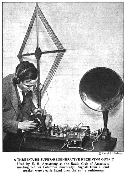
   1  Loop antenna having 12 turns each 3½ feet on a side.
   1  6-volt storage battery.
   4  to 6  22½-volt blocks of "B" battery.
   2  1500 turn honeycomb coils. (L3 and L4.)
   1  air core choke (L5). May be made by winding 300 turns of #28 insulated magnet wire on a form 4 inches in diameter.
   3  Variable air condensers having a maximum capacity not less than .001 MF. (C1, C3, and C4.)
   1  Fixed condenser, capacity .005 MF (C2).
   2  Filament current rheostats.
   2  Vacuum tube sockets.
   1  Pair phones.
   2  Amplifier vacuum tubes. These tubes must be of the hard variety. Soft, or gassy tubes will not function satisfactorily. The regenerator tube may be a Moorehead, Radiotron UV-202 or any one of the Western Electric tubes such as Types E, J, V, or L. The oscillator tube should preferably be one of the latter, though either Radiotron UV-202 or UV-203 may be used, preference being given the latter.
Figure 5
    The inductive coupler shown in Figure 5 may be made according to that sketch. Care should be taken to see that the windings of the "regenerator inductance coil" run in the same direction as those of the stationary coil of the tickler if the device is to be connected into the circuit as indicated in the sketch. In case this is not done, the terminals of the tickler may be reversed.
    With reference to Fig. 4, it will be seen that the condenser C4 is connected through the inductance L5 to the grid of the regenerator tube on the one side, and through the "B" battery to the filament circuit of this same tube on the other. The inductance L5 is interposed in this circuit to choke back the high-frequency currents of the regenerative circuit. Without this, these currents would pass through the condenser C4 and very effectually prevent operation.
    The action which takes place in this circuit has already been explained. However, it would appear from operation of the circuit as shown in Fig. 4 that in addition to acting as oscillator the second tube is also effecting some amplification, and this is quite possible. Full advantage of this possibility is to be taken in a later circuit.

HOW  TO  OPERATE  THIS  CIRCUIT
TO  PLACE this circuit in operation, insert a pair of telephone receivers between the "B" battery and the inductance L4. After lighting the oscillator tube, set the condenser C3 at a point near its full value. Follow this by adjustment of the filament current, plate battery, and condenser C4 until a high pitched audible note is heard in the telephones. If this is not forthcoming, look over connections. If it is forthcoming, the tube is oscillating at an audible frequency. This is as it should be. Remove the telephones from the plate circuit of the oscillator tube and close the circuit. Oscillations will continue. An easy way of doing this is by employing a telephone jack and plug, which will make a complete circuit even when the plug is withdrawn.
    To get final adjustments it will now be necessary to light the regenerator tube. The filament current and plate battery of this tube are also adjusted so that by advancing the tickler from a minimum toward a maximum value oscillations may be started. The presence of oscillations may be determined by placing the finger upon the grid terminal of the regenerator tube. If a decidedly pronounced click is heard, both when the finger touches and leaves the grid terminal, oscillations are in process.
    If a wavemeter is available it will come in handy at this time to those who are strangers to the circuit. Set it at the wavelength at which reception is to be effected and start the buzzer. Condenser C1 may then be adjusted for the approximate proper value, and the tickler brought into play for the amplification. If no wavemeter is available a given station may not be picked up so readily. Suffice it to say that when the condenser is set at about half its value, the circuits will be tuned to approximately 350 meters, providing directions as to construction have been followed. Attention is called to the fact that for regenerative action of the proper sort with this circuit much closer coupling between the plate and grid circuits of the tube is required than when the simple regenerative circuit is employed. In advancing the tickler from minimum toward maximum a point will be reached where a great hissing is heard in the telephones. Regenerative action is setting in at that point. Continue the advance of the tickler. The hissing noises will cease, or nearly cease, and it is at this time that the tickler coupling is adjusted to approximately the correct value. If this is borne in mind, the loop circuit may be varied over fairly wide limits in wavelength and the circuits at the same time kept in a fairly sensitive condition.

WHEN  THE  SIGNAL  ARRIVES
WHEN a signal is heard the best obtainable settings for strength should be made at C1 and with the tickler. All adjustments should then be gone over. Vary the filament brilliancy of the two tubes for maximum signal strength. Likewise, search for the best value of plate battery for each tube, and swing the loop into that position where signal is loudest. For, it must be remembered a loop receives best only those signals which advance in a direction parallel to its plane. Do not, however, expect too great directionality from the loop. The wires and coils in the circuits themselves, as set up on the table will pick up some energy. The energy picked up by the circuits on the table will not usually add to those picked up in the loop. Use of the circuit will soon indicate this fact. When this is taken into consideration the loop may always be swung through an arc of 180 degrees to ascertain in which position greatest signal is to be had.
    With further reference to Figure 4, this variocoupler may be assembled by setting a variometer of standard construction alongside and quite close to a coil similar to the regenerator inductance coil of the figure. For the standard variometer it will probably be necessary to use a 5-inch tube. In this case about twenty-eight turns of wire will suffice.

A  MORE  COMPLICATED  CIRCUIT
Figure 6
FIGURE 6 shows a further step toward increasing the effectiveness of the circuit. It consists in taking the signal out of the oscillator circuit instead of the regenerative circuit. In addition to its previous functions, the oscillator tube now acts as rectifier and amplifier. The potentials generated across the terminals of the inductance L 1 modulate a resultant of the oscillations of the oscillator tube. This is rectified, amplified regeneratively by the oscillator tube circuits, and again rectified with a considerable additional amplification as the result.
    The difficulties with this circuit are somewhat greater, the principal one being that, unless careful adjustment is made, beats occur between harmonics of the oscillator circuits and those energies which exist in the regenerative circuits. Also, since the telephones are in the oscillator circuit, the audible tone of the oscillator is heard at all times. The first is perhaps the most objectionable of the two from the experimenter's standpoint, for, if the pitch of the oscillator frequency is sufficiently high the ear will soon become deadened to it. But, from the standpoint of good quality of tone where voice or music is to be received, the latter is by far more objectionable, particularly where the third tube is added for the addition of a loud-speaking telephone.
    If an inaudible frequency is used in the oscillator circuit, amplification will be less, for the lower the frequency of this oscillation, the greater the amplification. A compromise must therefore be made between amplification and quality where it is desired to receive broadcast programmes. This compromise is somewhat mitigated by the use of a filter system which is interposed between the oscillator circuit and the telephones or amplifying tube, and so constructed and adjusted as to bar all tones above 3,000 cycles which is the upper limit of tone frequencies of the voice and of musical instruments.
    The construction of such a filter is not easy for the average experimenter, although the parts which it calls for may be purchased with little difficulty. The resistances R1 and R2 should be non-inductive and have a value of between 10,000 and 15,000 ohms. The inductance is made with an iron core and has a value of approximately 1 henry. The variable condenser has a maximum value of .005 MF. The circuit comprised by the variable condenser and inductance of the filter is adjusted for minimum oscillator tone in the telephones or loud-speaker.

A  COMPROMISE  FOR  BETTER  TONE  QUALITY
Figure 7
FIGURE 7 shows an arrangement for three tubes which is a compromise, the audio frequency amplifier tube being coupled into the regenerative circuit. This circuit will prove easier of operation, and, without the greater difficulties encountered in the circuit of Fig. 6, give good volume and quality.

FOUR  FUNCTIONS  WITH  A  SINGLE  TUBE
ATTENTION is called to the biasing batteries in the grid circuits of the tubes in the last mentioned figures. This battery needs to be variable in 1½ volt steps and to have a range up to about 6 volts. The use of these batteries gives considerable additional stability to the circuits and thus enables greater amplification.
Figure 8
    Figure 8 shows an extremely interesting application of the circuit. Here, one tube performs all functions,--regeneration, amplification, oscillation, rectification. Here one tube is used with very great effectiveness. The circuits are not particularly easy of adjustment but are recommended for trial to those who have found it possible to master the previous circuits.
    A careful study of the actions which take place in the super-regenerative circuit and a little patience will be rewarded. The combinations of the circuit which will be suggested to those who do understand the principles of action are unlimited. Only a few have been pointed out here, and it is to be expected that for months to come a great deal will be heard as to what has been done by countless amateurs with this new method.