Third Article: Tuned Radio Frequency and Neutrodyne
This is the last of a series of three articles in which Jack Binns, our radio editor, reduces apparently intricate radio circuits to first principles
SOMETHING about the name, "Tuned Radio Amplification," gives it an air of mystery. To the average fan the name conjures up visions of
controls and adjustments that only the expert can master.
To many who have dabbled with the ordinary form of transformer coupled radio frequency amplification, there seems to be no justification for "tuned radio." They cannot see why any one should add adjustable circuits where a fixed circuit apparently will work with supreme satisfaction.
Simplifying "Tuned Radio"
To clear up this question, and to show that tuned radio is by no means as complicated as it seems is my purpose in this article, the third of a series designed to explain various types of circuits by tracing their evolution from the original basic hook-up.
Of course, it is an easy matter to say that a thing is not difficult, but it a quite another matter to prove that assertion. In this case I shall attempt to prove my contention first by considering the very simplest circuit as a means of illustration.
If we place a variometer in series with an aerial and ground, then place a crystal detector and a pair of telephones across it, we shall have a complete radio receiving set that will work over a distance of at least 25 miles.
Let us analyze this circuit and its operation. When we turn the rotor coil of the variometer to a certain position, we hear the speech or music that is coming from the nearest broadcasting station.
Naturally the wave-length range of such a receiver is extremely limited, and will be determined by the maximum and minimum inductance represented by the range of settings on the variometer. How does such an instrument, so very simple in itself, work satisfactorily? When we have clearly understood this, we shall be able to comprehend the action that takes place in "tuned radio."
In the first place, the electromagnetic waves that surge through the ether from the aerials of the broadcasting station consist of an alternating current wave with a tremendous high frequency. In other words, electricity is passing though the cycle, negative to positive, and back to negative again at a rate of about a million times a second.
This terrific rate of change is referred to as "radio frequency" because it is far above the range of variation that comes within the audible scale. A wave that is alternating at such high frequency introduces the phenomenon of electrical resonance, and in order to record it we must have a circuit that is capable of resonance.
The primary requirements of such a circuit are inductance and capacity. The former is obtained by means of a coil of wire, the latter by means of a condenser.
The remarkable thing about the circuit is that there must be a certain balance between capacity and inductance for every wave length--in other words, for every frequency. All such circuits that combine inductance and capacity are called "oscillatory circuits."
"That is all very well," you may say; "but where do you get the capacity with only a variometer?"
The answer lies in the fact that in every piece of wire there is a quality known as "distributed capacity." If we wind this wire in the form of a coil, and put insulation around the wire, we shall find an appreciable amount of capacity in the circuit represented by the winding.
Variometer Will Help
In this case we obtain our tuning by varying the amount of inductance in the circuit, without interfering with the total capacity of it. Such a method of tuning is practical and efficient. Under such circumstances a variometer is a very efficient tuning instrument, provided too much is not expected from it.
After we have grasped the underlying principles in the action of an oscillatory circuit, we can proceed to an explantion of the difference between transformer coupled radio amplification, and "tuned" radio amplification.
If we impress an alternating voltage across the grid and filament of a hard vacuum tube, an equivalent of the voltage will be reproduced in the plate circuit, provided the right constants exist in the plate circuit. There will be this difference, however--the reproduction in the plate circuit will be many times stronger because of the amplifying characteristics of the tube itself.
Radio frequency transformers are designed to pass this amplified current along to the next tube for further amplification. In the very nature of things these trans formers are designed to cover a fairly large wave-length band. In other words, they must cover a wide range of frequencies, otherwise separate transformers would have to be inserted in the circuit for each individual broadcasting station. This being the case, the transformer will be more efficient on the frequency to which it is nearest in resonance than it will on any of the other frequencies it passes. This is a disadvantage that in practice is offset by the fact that the transformers are automatic in their action, and do not require adjustment. It is in this respect that "tuned" radio amplification really the most satisfactory, because what we really do with such a system is to tune each of the circuits into resonance with the wave we are receiving. The result is that we obtain the maximum possible amount of amplification, the maximum transfer of energy from one stage to another, and the maximum amount of selectivity.
The ability to obtain maximum selectivity is apparent. Each stage acts as a sieve, allowing only those currents that are in exact resonance to pass through, and stopping the others. The drawback, of course, lies in the increased number of adjustments necessary.
Now, if we examine various diagrams of simple receivers, we shall observe that in addition to the variorneter circuit described in the beginning of this article, we can have a double circuit that can be quite an elaborate affair. For example, it can consist of a variocoupler with a variable condenser in series with its primary winding, and another condenser across its rotor winding. Under these conditions it will have four different tuning elements: First, the setting of the series condenser; second, the number of turns of wire put in use in the primary; third, the degree of coupling between the two coils; and, fourth, the setting of the second condenser.
Similarly the interstage coupling of a radio frequency amplifier can be made simple or complicated, as desired. The more adjustments used, the more accurate will be the resulting tuning, and the more expert will be the handling required. In practice, a multiplicity of adjustment is not necessary. In fact, a variometer in each of the circuits will be sufficient, provided the variometers are designed to cover the wave length band to be received.
Difference Lies in Grid Circuit
Such is the basic system of "tuned" radio amplification, a circuit diagram of which is shown in Fig. 1, on page 61. A glance at the diagram reveals that for all practical purposes the method of coupling the different stages is almost the same as that employed in audio frequency amplifiers.
The main difference lies in the grid circuit when a plain variometer is used. In this case the B battery is joined to one side of the variometer. We could not connect it direct with the grid, for if we did so, we should be impressing the full B battery voltage across the grid and filament of the succeeding tube, preventing operation.
This difficulty is overcome by inserting a by-pass condenser in series between the plate side of the variometer and the grid of the next tube. This condenser is a fixed one, and will readily pass the radio frequency currents in the circuit, at the same time effectively stopping the direct current of the B battery from reaching the grid circuit.
If more than one stage of "tuned" radio is employed, and the variometer type of coupling used, it will be found that every variometer actually in a plate circuit can be calibrated for wave length, and settings made accordingly for reception from any station. To accomplish this, the dials must be fitted carefully to the shafts, so that relative positions of the dial and rotor will remain unchanged.
Under these circumstances, tuning can be accomplished in the same manner that a safe is opened--by means of a combination. The method of procedure is as follows: Set the plate variometers in the same position, and make the final tuning with the aerial variometer. When stations have been heard, record the reading of the dials on a chart. The same stations can be found again in the same recorded positions.
Explanation of this simple tuning scheme brings us to a consideration of the most remarkable invention of the year--namely, Professor Louis A. Hazeltine's neutrodyne principle. This system is simply tuned radio frequency amplification, with the squeal removed.
In my article last month I pointed out just how regeneration was present in radio frequency amplification. Unless the transformers are correctly designed, this regeneration is a distinct disadvantage and prevents clear reproduction.
Professor Hazeltine's very ingenious invention eliminates this disadvantage by adopting a well known principle that two equal forces neutralize each other. New the regenerative action in a radio amplifier is caused by the internal capacity existing between the plate and grid elements inside the vacuum tube. While this capacity is extremely small, it is disastrous under certain circumstances. In the neutrodyne system it is eliminated by pitting against it another capacity of equal value. These two capacities neutralize each other, thereby destroying the troublesome capacity effects.
Having achieved this important result, Professor Hazeltine was able to take advantage of other known laws until he obtained a step-up ratio in the windings of the interstage transformers. These transformers have four times as many turns of wire on the secondary as they have on the primary. The result is that in transformation the secondary voltage is stepped up four times, which, of course, gives further amplification. Another important feature of the transformers is the novel method of tuning them into resonance with the incoming wave. This is done entirely by means of condensers placed across the secondary coils, with the result that the number of controls is reduced. Here the inventor has taken advantage of the laws governing coupled coils. If this coupling is extremely close, the total inductance of both coils will exist in each circuit, so that, while there are actually but 15 turns of wire in the plate circuit, the total amount of inductance will be equal to the total in the transformer.
This novel adaptation of electrical laws permits an efficient coupling of the different stages, and makes it unnecessary to insert any by-pass condensers in the grid circuit of the amplifiers.
An Important Point
An important point to remember in the neutrodyne circuit is that the secondary coil must be wound on the outside of the primary coil. The object is to screen away some of the coupling capacity that otherwise would exist between the primary coil of one stage and the secondary circuit of the preceding stage. Another point is that the transformers must be set at an angle of 45 degrees, at least six inches apart from each other, in order that they will not be in the electromagnetic field. of each other.
These, however, are only variations of the basic system of "tuned" radio. A glance at the diagrams of the two systems will show how both are much alike, and it will bear out the fact that I have tried to emphasize in this series--that all circuits have a definite reason for existence, and that ail are based on the same fundamentals.
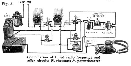
The third system (Fig. 3) shown on this page is a simple "tuned" radio reflex circuit. In the September article I explained in detail the reflex system. The circuit shown here is unquestionably the simplest of the reflex adaptations. It is one with which we have experimented extensively and which has given very good results, both as a distance getter and a volume giver.