The Model TO were purchased for installation in battleships for tactical communications and the Model TP for fleet and force flagships and battleships for general communications.
No. Model Contract
yearContractor 21 TO 1923 Westinghouse Electric & Manufacturing Co. 1 TO 1923 Washington Navy Yard. 23 TP 1923-25 Western Electric Co. 5 TU-1 1923 General Electric Co. 8 TU-2 1923 Western Electric Co.
These transmitters were used for broadcast schedules with the fleets.8
Station Contractor Year Power Frequency range Arlington Washington Navy Yard 1923 10 64-118 Arlington Washington Navy Yard 1924 20 86-112 Arlington Washington Navy Yard 1923 3 100-500 San Diego General Electric Co. 1924 80 25-35 Cavite Navy Yard, Mare Island 1924 6 56-355 Hawaii Navy Yard, Mare Island 1924 6 56-355
The frequency allocation proposed by the Navy for its use is a scientific and systematic allocation. The plan permits an economical utilization of the ether.During the summer and fall of 1925, advantage was taken of the U.S. Fleet cruise to Australia and New Zealand to test the use of high frequencies for ship-shore communications. These tests, conducted under the supervision of Taylor, demonstrated the superiority of low-powered, high-frequency transmission for long distances. On 5 November 1925, final decision to include high-frequency equipments in the radio modernization plan was made.13
For peace use it gives consideration to the requirements of Government and non-Government activities and is in accord with the band allocation approved by the Fourth National Radio Conference.12
The use of a selective non-interfering system permitting the simultaneous use of the required number of communication channels.A study of the type installations shows that the plan included providing high-frequency equipments to all fleet and force flagships, battleships, first-line aircraft carriers, heavy cruisers, first-line light cruisers, first-line fleet submarines, and large patrol vessels.
The character of individual ship installations to be such as to permit efficient handling of battle and strategic communications.
The equipment installed to be such as to permit the required expansion necessitated by aircraft, long-range firing, and increase in size of the fleet with its consequent decentralization of command.
The location of radio spaces and the installation of interior communications for radio to be as prescribed by the report of the Ship Control Board, 1924.
The provision of accurate means of equipment calibration and frequency measurements in order to maintain the reliability of the selective system.
The provision of rugged, reliable, operationally simple equipment which will maintain, within a small percentage, stability under the adverse conditions encountered on board ships.
The standardization of installations, making for increased flexibility, economical purchasing, and maximum intercommunications between the various types of vessels.
The utilization of high frequencies wherever possible in order to save weight and space and for economy.
A scientific fleet radio frequency plan which reduces interference to a minimum and requires a minimum of channel shifting with changes in cruising and battle dispositions.
That the plan will be carried out in annual stages consistent with congressional appropriations and the ability of manufacturers.
| Heterodyne | Receivers | Transmitters | ||||||||||||||||
| Frequency | RE | RF | RG | TU | TV, TW, TX1 | XA2 | XC | |||||||||||
| meter | ||||||||||||||||||
| Battleships | 18 | 18 | 18 | (3) | 18 | (2) | 18 | 2 | ||||||||||
| Cruisers | 16 | 1 | (2) | 3 | (3) | 3 | 10 | 11 | 3 | |||||||||
| 16 | 10 | (2) | 10 | (2) | ||||||||||||||
| Destroyers | 103 | 1 103 | 103 | 38 | 4 5 50 | 95 | ||||||||||||
| Minelayers | 8 | 8 | 6 | |||||||||||||||
| 2 | (2) | |||||||||||||||||
| Aircraft carriers | 3 | 3 | 1 | (2) | 2 | (6) | 2 | 2 | (2) | |||||||||
| 2 | (6) | |||||||||||||||||
| Auxiliaries | 18 | 91 | 17 | (3) | 18 | 6 18 | 8 | 2 | ||||||||||
| 37 | 1 | (2) | ||||||||||||||||
| Fleet submarines | 4 | 4 | 4 | 4 | 6 3 | 4 | ||||||||||||
| Gunboats | 6 | 6 | 6 | 6 | 1 | 8 | ||||||||||||
| Total5 | 176 | 251 | 311 | 139 | 83 | 140 | 8 | 8 | ||||||||||
| NOTE.--Number in parentheses indicates number of sets if more than 1.
1 Basically, these 3 transmitters were identical and should have been designated TV, TV-1, and TV-2. 2 All ships in this column are fleet and force flagships. 3 This was later changed to provide 1 for each destroyer squadron and division leader. 4 3 previously equipped. 5 50 additional TU transmitters to be purchased during fiscal year to complete installations in 3 destroyer squadrons. 6 1 previously equipped. | ||||||||||||||||||
In addition to the above, this ambitious program included:
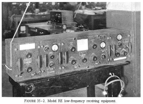
Frequency Bands Receivers: RE 10-100 kc. RF 75-1,000 kc. RG 1,000-20,000 kc. Transmitters: TU 195-565 kc. TV-TW-TX 2-3 mc. XA 4,000-4,525 and 2d and 3d harmonics XC 4,000-4,525 and 2d harmonic.
Duplexing the radio installations in seven battleships, three cruisers and eight auxilliaries.The program rejected the recommendation of the Commander in Chief, U.S. Fleet, concerning the upper limitation of frequency usage to 9 mc. Equipments capable of working on frequencies up to 19 mc. were made part of the requirements. In support of this program for the fiscal year 1926, Congress appropriated $550,000.20 This sum was far more in keeping with the amount which could be spent than the previously appropriated $1½ million, much of which lapsed. The equipment in the above table was placed under contract.
Installation of break keys and the improvement of radio direction-finder installations and the provision of auxiliary power source for emergency transmitters on all destroyers.
Fitting all submarines with coil antennas.
Provision of field strength and antenna measuring instruments to all ships.
Provision of battery-charging equipment to all ships.
Service tests of experimental 5-kw, high-frequency and 5-kw. continuous-wave intermediate-frequency transmitters on designated ships.
Provision of trap units for receiver installations on all duplexed ships.
Provision of crystal-controlled frequency indicators for models TV, TW, and TX transmitters and model RF receiver.19
Flagships of units requiring long-distance communications.This policy was approved on 31 March 1927 by the Chief of Naval Operations.23
Light cruisers, first line.
Minelayers, first line.
Destroyer leaders.
Fleet and minelaying submarines.
Large patrol vessels.
Vessels on special service, when authorized.
Fleet requirements for communication channels;This revision was approved by the Chief of Naval Operations on June 1929 and, with modifications due to improved equipments, remained the primary guidance for ship's radio installations until the beginning of World War II. The necessity of providing high-frequency radio communications to all combatant vessels of the Fleet was recognized for the first time.30
Individual ship requirements for communication channels;
Intercommunication requirements between all types of naval ships and aircraft and naval shore radio stations, foreign radio shore stations, U.S. Army, and merchant marine;
Wartime utilization of the regular merchant-ship radio installations;
Standardization of equipment to facilitate maintenance and for economy in providing spare parts;
Probable grouping of ships in task forces and groups;
The fleet radio frequency plan;
The report of the Ship Control Board;
National and international laws and regulations and treaties pertaining to radio, navigation, and safety of life at sea;
U.S. Army and Coast Guard radio plans;
Space, weight, and personnel limitations aboard ship;
Technical design limitations; and
The use of radio by foreign navies.
50 models TAF-2, TAO, TAR, TAR-2, and XF-1 high-frequency transmitters were installed in battleships, aircraft carriers, light cruisers, fleet submarines, and destroyer tenders;In addition, the duplexing or modernization of the radio installations of the U.S.S. California, Oklahoma, Nevada, Tennessee, Arizona, Pennsylvania, and Vestal were completed. Complete radio installations for 34 "S" type submarines, direction-finder equipment for 82 destroyers and auxiliaries, and Model TAK transmitters for 8 battleships were installed. Fifteen TAQ-2, 1 TAR-1, 33 TAR-2, 30 TAT-1, and 3 XP-l transmitters were purchased during the fiscal year for ship's installations. Other projects were completed to improve efficiency and flexibility.31 The replacement of the destroyers of two squadrons by destroyers from the reserve fleet facilitated the modernization of their radio installations. More was accomplished toward the provision of adequate, flexible, reliable fleet communications during the 1930 fiscal year than during any other like period of time.
119 models TU-4, TAH, TAJ-1, TAP, TAQ, and TAQ-1 low-frequency transmitters were installed in battleships, aircraft carriers, aircraft tenders, light cruisers, destroyers, submarines, survey vessels, and various types of tenders, tankers, and supply vessels;
44 models TAD-1, TAD-2, TAP, and TAT medium-frequency transmitters were installed in battleships, aircraft carriers, destroyers, minesweepers, tenders, and other supply vessels;
49 models TAV and TAV-1 medium-frequency portable field transmitters were issued to major units of the fleet;
20 RO-RP low-, medium-, and high-frequency receivers were fitted in submarines;
15 RQ (15-20,000) kcs. receivers were fitted in minesweepers;
30 DG radio direction finders were installed in battleships, light cruisers, and auxiliaries; and
Major fleet units were provided with Model LB heterodyne frequency indicators and crystal-controlled calibrators.
"Among the complaints--the submarines had only one radioman and most commanding officers thought they should have more. Commander Blue destroyers said there were too many radio messages, his flagship sent, received or intercepted 95 messages during the problem."
KC Protective Screen (Submarines) 444.4 Outguards 375 Pickets 277.8 Bombing Detachment 250 Supports 209.1 CinC Long Wave 76